


All the electronics of BlueCArd (a fully 3D printed Arduino Bluetooth RC car controlled with Android) are put in a circuit on a solderless breadboard. In this blog post, I’ll explain what a breadboard is and how to use it. I’ll put all the electronics on a breadboard, so it is essential that everyone is on the same page on this.

In the last post, I listed all the elements I used to build the 3D-printed Arduino-based RC car – BlueCArd. The first element in the list is a breadboard and in this post, I’ll explain in short what a breadboard is and how to use it.
I also made a short video, where I explained the breadboard and connected a simple circuit to demonstrate its use. You can watch the video here:
Breadboards are maybe the most fundamental piece when You start learning about electronics. They are also perfect for prototyping and testing different circuits and rapidly changing and extending the circuit.
The breadboard is a solderless board where you can put and connect elements without soldering them. This enables rapid prototyping and easy changes.
The name “Breadboard” comes historically from the past when the electronic was big and bulky and people just took a real breadboard for cutting bread, put some nails in it, and connected the tick wires.
Now the breadboard is a standardized element with predefined pin holes where the electronic elements can be connected.

For the BlueCArd circuit, we will use the half-sized 400-pin breadboard from the picture above.
The breadboard consists of 2 middle parts and two outer parts.
The outer parts are for the power supply and are connected vertically all the way through the board. This means that all 25+ and all 25- pins are connected.
The middle parts are for elements and are connected horizontally. This means that the pins from A to E and from F to J are connected for every row.
A picture is worth a thousand words, so let’s look at this example for a better understanding:

- The power supply is applied to 2 pins in the right vertically power supply row. You can see that all the pins vertically are now marked green because they are connected to each other and with the battery pack.
- The resistor is connected to row 10 and row 17. The pins here are marked green horizontally, meaning that all the pins from F to J on row 10 and row 17 are connected to the resistor.
- The LED is connected to the resistor on row 17 (+ side) and to the battery (- side) on row 20.
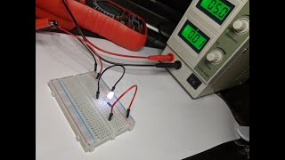
In this way, the circuit is finished, and the LED will emit light like in the picture below.
Here I use a laboratory power supply because it is much more convenient than a battery pack and you can set the required voltage as you wish. Of course, you can use a battery pack for this, if you don’t have a laboratory power supply.
There are 2 important things to be aware of when connecting an LED:
- LED is a diode (it’s literally in the name) so the direction is important. You have to connect the plus side to the plus side of the power supply. The plus pin on a LED is easy to spot. It is always longer than the minus side!
- LED is driven by current. This means that without a current limiter, it will burn out. You have to always connect a resistor. To calculate the resistor, you can use this formula: R = (Src V – LED V) / desired LED current.
In the picture above you can see that the circuit uses around 10 mA. The LED needs around 3.2V. With this data, you can calculate the needed resistor.
One more advantage of using the laboratory power supply is that You can limit the supplied current. E.g. I set the max current in the picture above to 20mA. In this way even if I make a mistake and increase the Voltage or forget the resistor the LED will not get more than 20mA and will not burn out.
This is especially helpful when working with more expensive modules (like the Arduino or the BLE module).
Btw. I bought this laboratory power supply for something like 40 bucks on Amazon.
This is all you need to know about breadboard to build the BlueCArd!
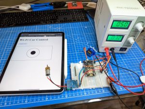
In the next post, I’ll show You how to put the Arduino Nano on the breadboard, connect it to the computer and run a simple sketch to control the LED we just put on the board.


Leave a Reply
You must be logged in to post a comment.