


The ultimate goal is to build the BlueCArd (a fully 3D-printed Arduino RC car). For the electronics of BlueCArd, I use an Arduino Nano-compatible board.
In this Tutorial, I will explain in short the Arduino Nano board, connect it to the computer with a USB cable, create a circuit, and finally write a sketch and run it on the Arduino.

The elements used in this tutorial are from the list of elements needed for BlueCArd. The detailed list can be found here:
The elements needed for this tutorial are:
- 1x half-sized breadboard (400 pins)
- 1x Arduino Nano-compatible microcontroller
- 1x USB mini-B cable
- 2x pin connector cables (one red and one black)
- 1x resistor (around 200 Ohm)
- 1x LED (white, for other colors the resistor should also be changed!)
I bought the cheapest Arduino Nano-compatible board I could find. The unsoldered version was cheaper, so I bought it instead of the one with soldered pins. I made a video of how I soldered them. You can watch the video here:
Software needed: Arduino IDE – download for free from the Arduino site
You can also watch the step-by-step video version of this tutorial here:
Some Theory
I already described the breadboard in the previous post here: What is a Breadboard and how to use it
Here this is only a short overview of the Arduino Nano microcontroller. I will describe only the most necessary stuff, that You need to know about, to complete this project (and maybe most of the other projects out there)
Looking from the top the Arduino Nano looks like this:

The analog pins are for sensor input (and only for input), so we will not need them for this project.
Even the analogWrite() function uses the digital pins and writes a PWM wave to a digital pin instead of an analog value.
The digital pins can read and write values and this is all we need.
The rest, which I marked in the image above, is just the power supply. For this, I use the ground and the VIN pin.
Step 1 – the breadboard
Plug the Arduino Board into the breadboard like in the image below:

The Arduino pin D12 should be plugged into h1 on the breadboard.
The Arduino pin D13 should be plugged into d1 on the breadboard.
The Arduino pin TX1 should be plugged into h15 on the breadboard.
The Arduino pin VIN should be plugged into d15 on the breadboard.
Step 2 – Connect the Arduino Nano board to the computer
Connect the mini-B USB connector of the USB cable to the USB port on the Arduino.
Connect the other end to your computer.
The Arduino Nano board should be powered on (the PWR LED should be on).
Step 3 – Configure Arduino IDE
Start the Arduino IDE – it should show a simple sketch like in the image below:

Now from the menu Tools select
Board: Arduino Nano
for the Processor if original:
Processor: ATmega328P
if not original try:
Processor: ATmega328P (Old Bootloader)
The Port should be selected automatically. If not select the right one.
Now click Open -> generated_examples -> Blink
A new window with the following code should appear:
1 2 3 4 5 6 7 8 9 10 11 12 13 | // the setup function runs once when you press reset or power the board void setup() { // initialize digital pin LED_BUILTIN as an output. pinMode(LED_BUILTIN, OUTPUT); } // the loop function runs over and over again forever void loop() { digitalWrite(LED_BUILTIN, HIGH); // turn the LED on (HIGH is the voltage level) delay(1000); // wait for a second digitalWrite(LED_BUILTIN, LOW); // turn the LED off by making the voltage LOW delay(1000); // wait for a second } |
Here the LED_BUILTIN is the “L” LED on the Arduino Nano board.
Now click the Upload button. If everything goes smoothly the Arduino IDE should look like this:

with a “Done uploading.” message and some info about the sketch size etc…
The “L” LED on the Arduino should be blinking now (1 second on / 1 second off).
Step 4 – understanding the code
Arduino sketches are really simple. There are only two functions:
void setup() {…} -> called only once at the start to do the needed initializations.
void loop() {…} -> called repeatedly as fast as the Arduino can. Most of the code will be here or will be called from here.
As I wrote above, the digital pins can be in Input or Output mode. This can be set with the pinMode() functions.
In the code above the LED_BUILTIN pin is initialized in Output mode in the setup() function.
In the loop() function the LED is then switched On or Off. This is done with the digitalWrite() function. The value of the digitalWrite() function can be either HIGH (5V) or LOW (0V).
The delay() function just blocks for the given time. The delay() function may look very convenient, but it is a bad function because it blocks everything for the given time. Because of this, it can be used only in very simple programs. I’ll talk about alternatives in a later post.
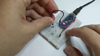
Step 5 – controlling an external LED
First, we have to build the circuit. The good news is that this is the same circuit we already build in the last tutorial: https://www.thinker-talk.com/bluecard-a-fully-3d-printed-arduino-rc-car-part-2-what-is-a-breadboard-and-how-to-use-it
The only difference is that we will supply the power to the LED from the Arduino Nano board.
To do this connect the minus side (the black cable) of the LED to the GND pin of the Arduino board and the plus side (the red cable) to the D9 pin of the Arduino board.
D9 is chosen at random, you can use any other pin if you like. If you do this the chosen pin has also to be changed into the sketch code!
The circuit should look like this now:

Important: don’t forget the resistor or the LED and the Arduino pin can be damaged!
The LED is now integrated into the circuit. All that is left is to change the LED pin in the sketch code and test it.
To do this we have to change LED_BUILTIN with the LED pin number where we connected the LED. In our caste, this is the number 9. We can just change LED_BUILTIN with this number, but a better way is to define a constant e.g. MY_LED with value 9 and change LED_BUILTIN to this constant. In this way, we can later easily change the LED pin without having to search in the code all the places we use it.
The code should look now like this:
1 2 3 4 5 6 7 8 9 10 11 12 13 14 15 | const int MY_LED = 9; // the setup function runs once when you press reset or power the board void setup() { // initialize digital pin LED_BUILTIN as an output. pinMode(MY_LED, OUTPUT); } // the loop function runs over and over again forever void loop() { digitalWrite(MY_LED, HIGH); // turn the LED on (HIGH is the voltage level) delay(1000); // wait for a second digitalWrite(MY_LED, LOW); // turn the LED off by making the voltage LOW delay(1000); // wait for a second } |
Connect the Arduino Nano board to the USB cable and click upload.
The result should look like this:
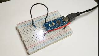
Congratulations! You completed your first Arduino circuit!
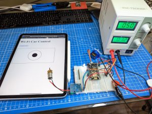
In the next tutorial, I’ll explain what a DC-DC boost (step-up) converter is, why we need it, and how to use it.
Previous: BlueCArd part 2 – What is a breadboard and how to use it
Next: BlueCArd part 4 Boost Converter – what is it and why do we need it


Leave a Reply
You must be logged in to post a comment.