


A detailed list of all the elements needed to build this 3D printed, Bluetooth-controlled (mobile phone with android) RC car.

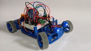
BlueCArd is a fully 3D-printed indoor RC (remote-controlled) car powered by an Arduino Nano microcontroller, and a Bluetooth module, and controlled with an Android device.
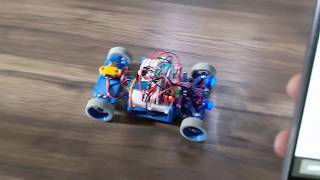
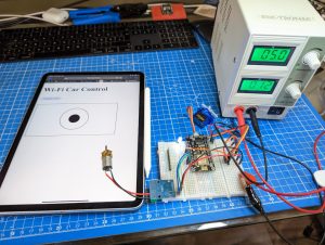
You can watch the car in action in this short teaser video:
The brain of the car is an Arduino Nano-compatible microcontroller. For communication, the car uses a BLE (Bluetooth low energy) module.
I wanted to make the car as easy to build as possible and as cheap as possible. To achieve this, I use only standard elements and go without anything that is not absolutely necessary.
For the remote control, I decided to use BLE, because it is very convenient (no pairing needed) and as a remote controller, I can use any android device with Bluetooth (any modern android phone or tablet).
Except for the electronics and the motors, the rest is 3D printed. I designed everything by myself and tested and printed it on my Prusa i3 MK3s printer. Even the tires are 3D printed. For them I used TPU, the rest is printed in PLA.
Some of You with a Bowden-type extruder may have a problem printing TPU. If this is the case, just put some rubber bands directly on the rims.
I will upload all STL files (3D models) to Thingiverse and add the link here.
The Android and Arduino projects are on GitHub and can be downloaded here:
https://github.com/nenovmy/ardcar.git
The 3D printable elements are on Thingiverse here:
Arduino Bluetooth RC Car controller from Android
Below is a detailed list of all elements I used to build the RC car.
You can find a short elements overview video here:
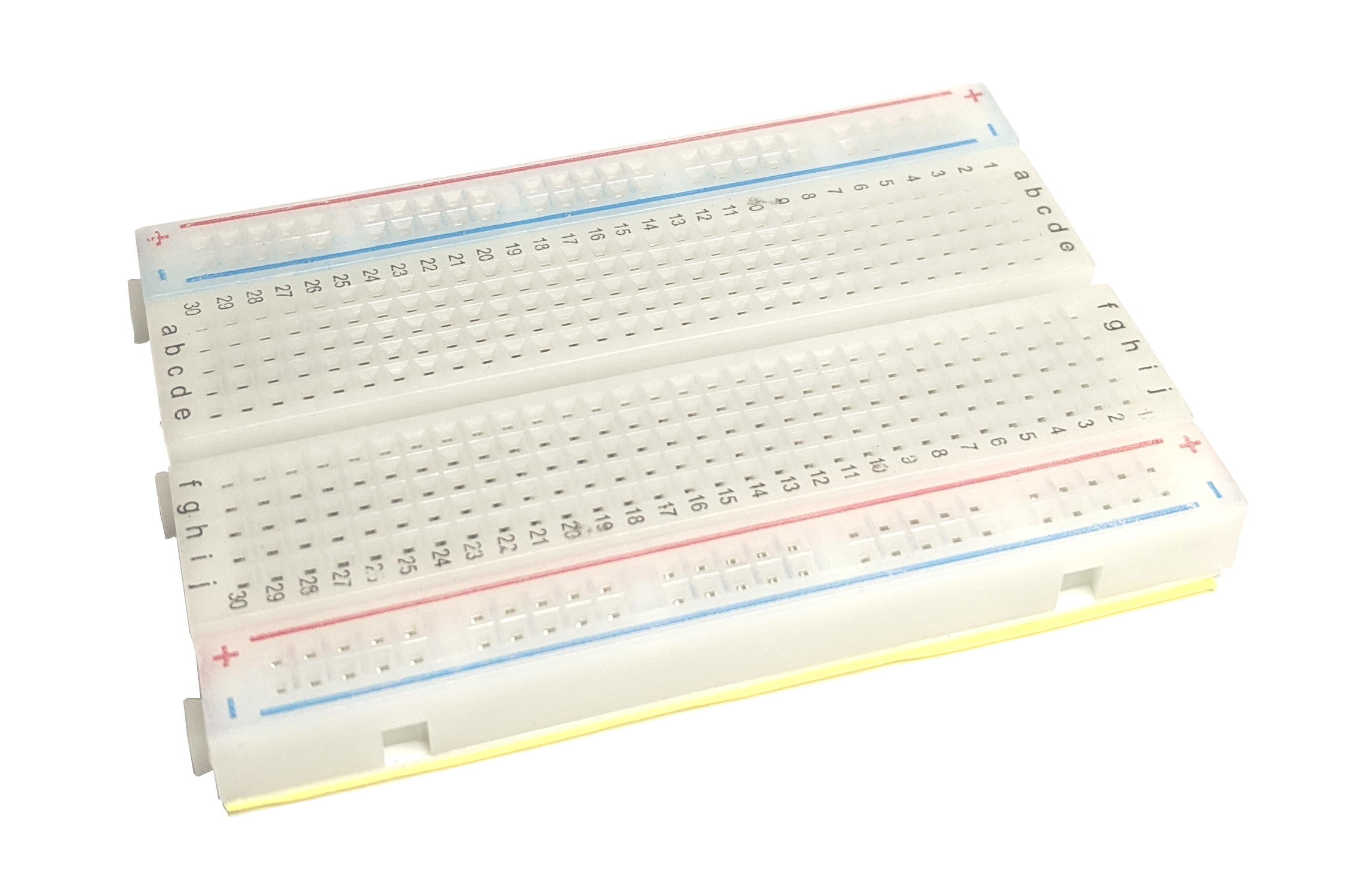
1x Half sized breadboard (400 pins). I designed the main body for this breadboard size.
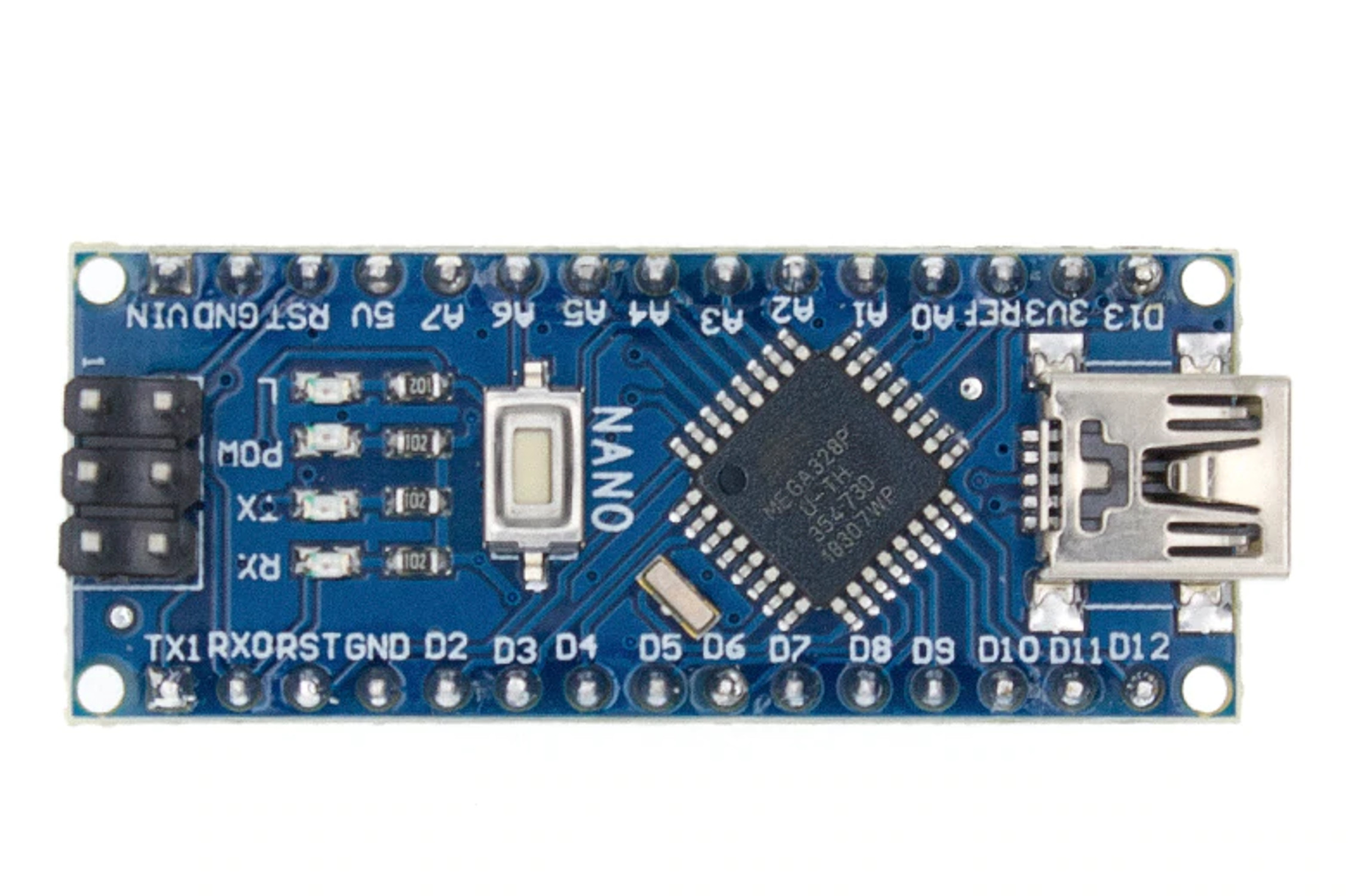
1x Arduino Nano compatible board (one with ATMEGA328P chip.)

1x AT-09 / HM-10 BLE 4.0 Bluetooth module. (Also a cheap clone)

1x DC-DC Step-Up (boost) converter. This one can convert any input voltage between 1V and 5V to 5V and can deliver up to 600mA current.
This is needed to convert the battery voltage from (3×1.2V =) 3.6V to 5V.
I soldered pins to this one to use it on the breadboard.
It is important to deliver 5V and at least 500mA
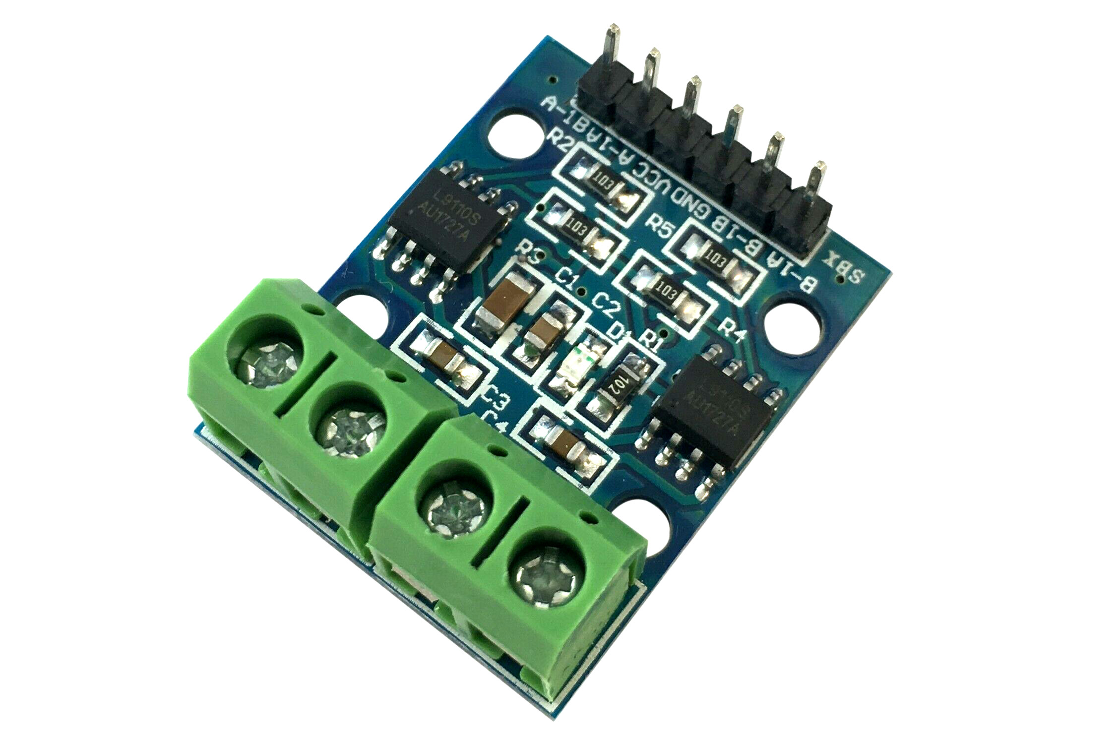
1x H-Bridge to drive the DC motor. I bought this one, it has 2x L9110S motor control chips and can drive up to 2 DC motors or 1 stepper motor.
This one is needed, so we are able to reverse the motor direction. With a simple MOS-FET, we can only change the power, but not go in the other direction.

1x Small resistor for the LEDs. You shouldn’t connect the LEDs directly to the Arduino pins or You can damage it.
I used a 100 Ohm Resistor because this is the smallest I have.
You can calculate the needed resistor like this: R = (Src V – LED V) / desired LED I. In my case I have 2 white LEDs in parallel => R = (5V – 3.3V) / (2x 0.01A) = 85 Ohm
2x or 3x Resistors for the Bluetooth module. The Rx pin requires 3.3V, but the digital pins provide 5V. We have to lower the 5V to 3.3V with e.g. a voltage divider. For this we need Resistors 2:1 ((5V x 2R) / (2R + 1R) = 10V / 3 = 3.333V) . E.g. we can use one 1k and one 2k resistors. I don’t have 2k resistors at hand so I used 3x1k and connect 2 of them in series.
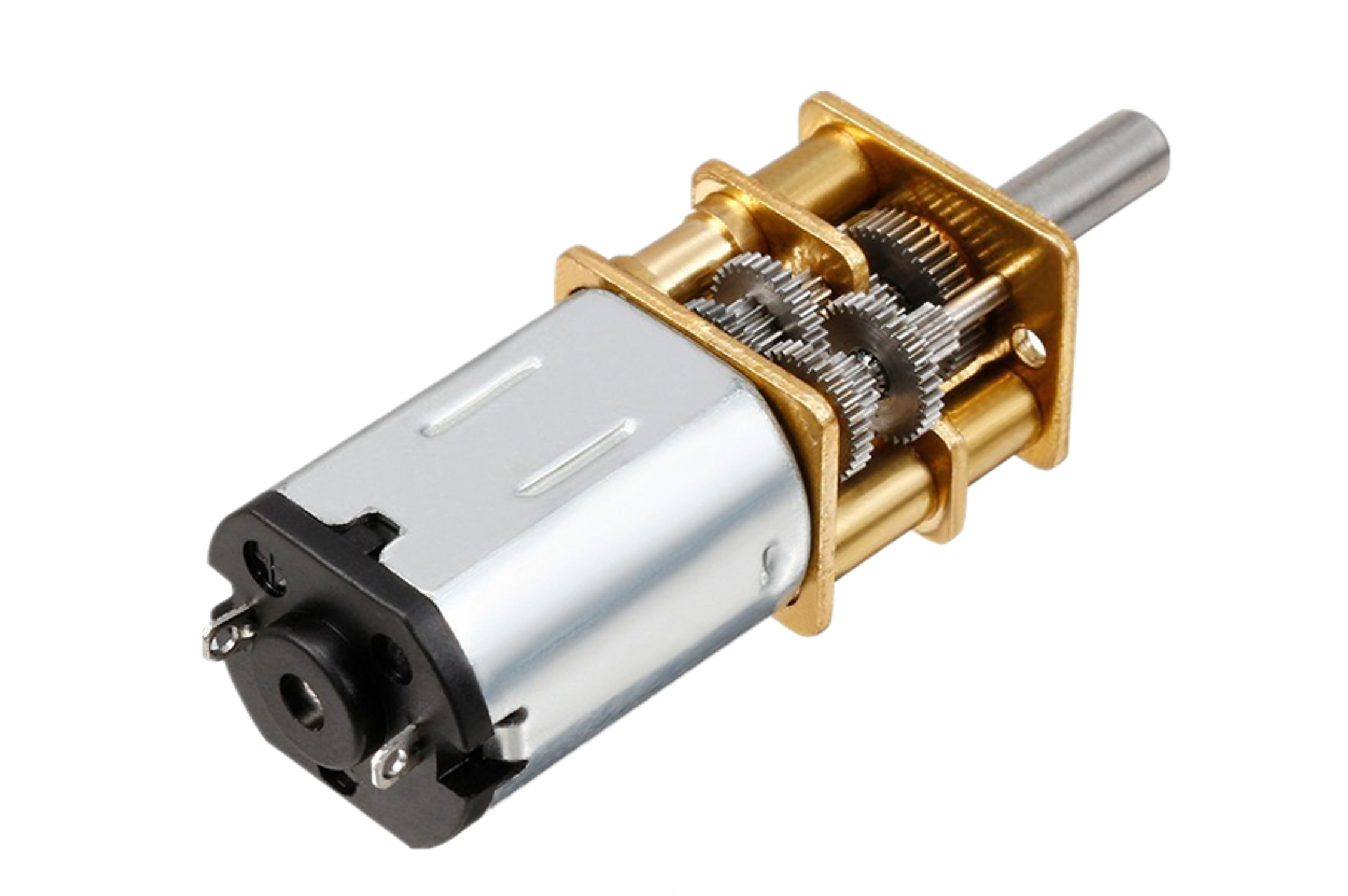
1x DC motor 5V. This one is for up to 6V.
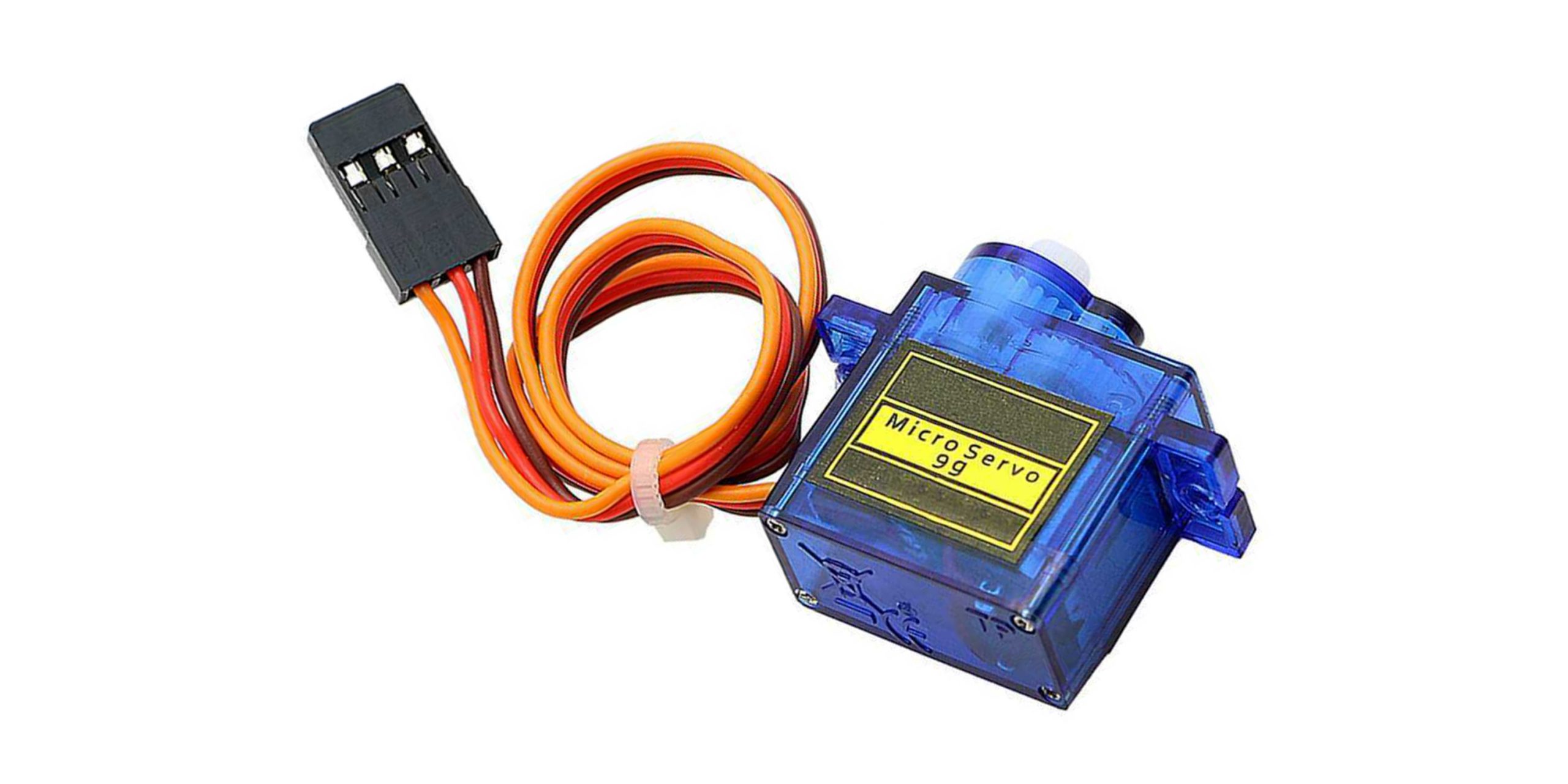
1x Servo motor for the steering. It must be like this one or it will not fit.
Also, there are 2 types of servos. Be aware not to buy a continuous servo motor. You can’t set rotation position to the continuous servos, only speed, and the steering is impossible.

1x Switch
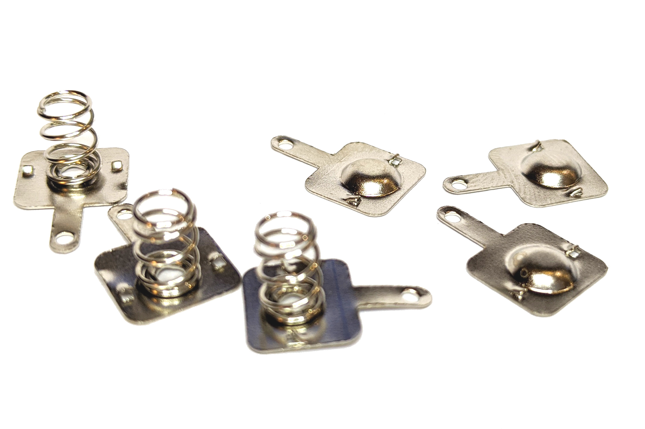
6x Battery shrapnel (3 positive and 3 negative contact pieces) for the battery pack.
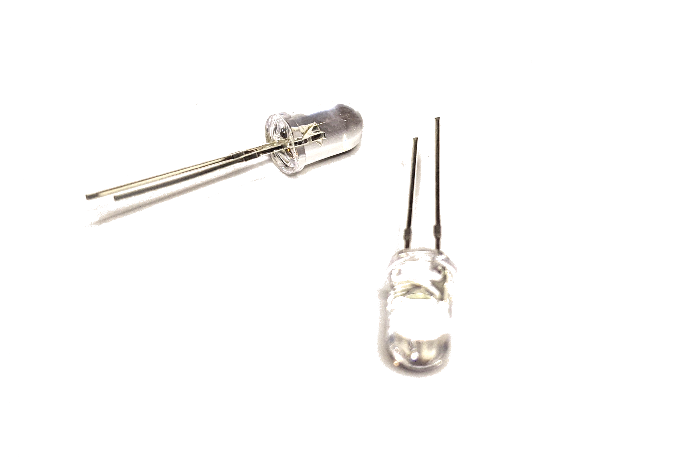
2x (white) LEDs
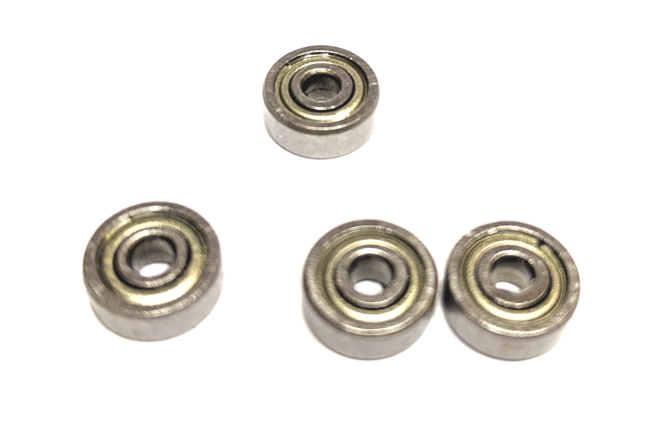
4x Bearings 3x10x4mm

Some wire, less than 50cm
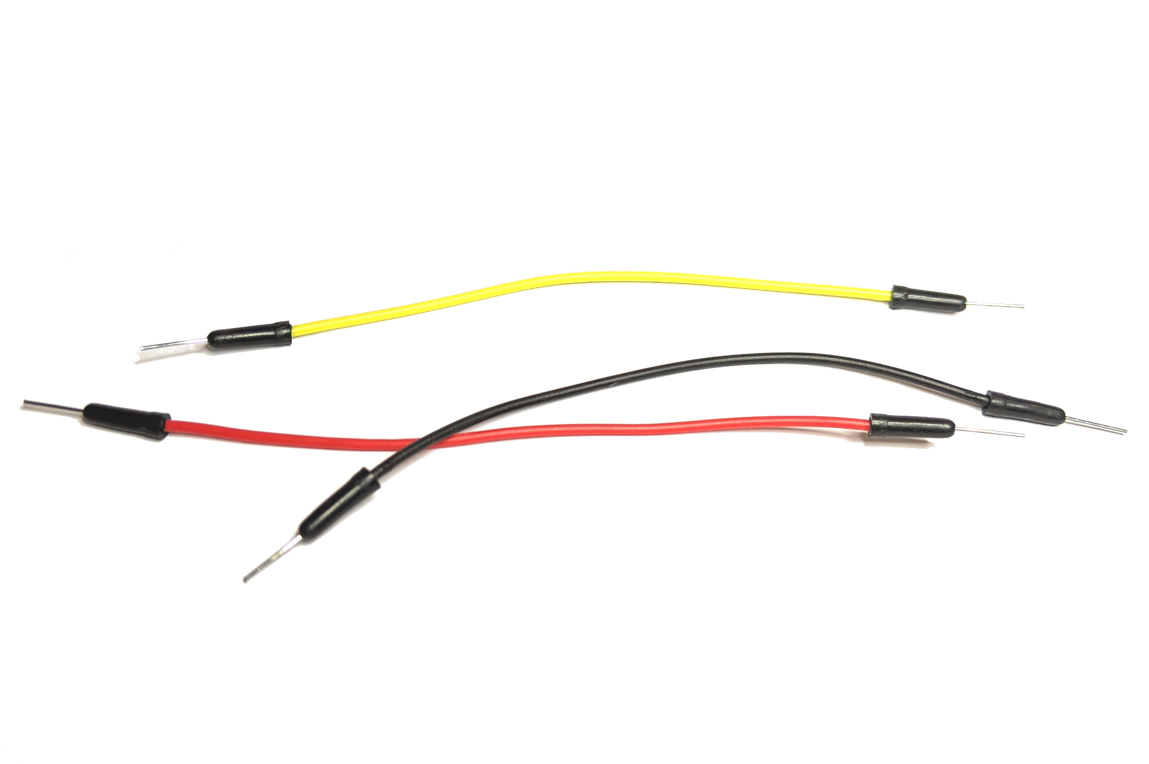
Around 20 pin-cables
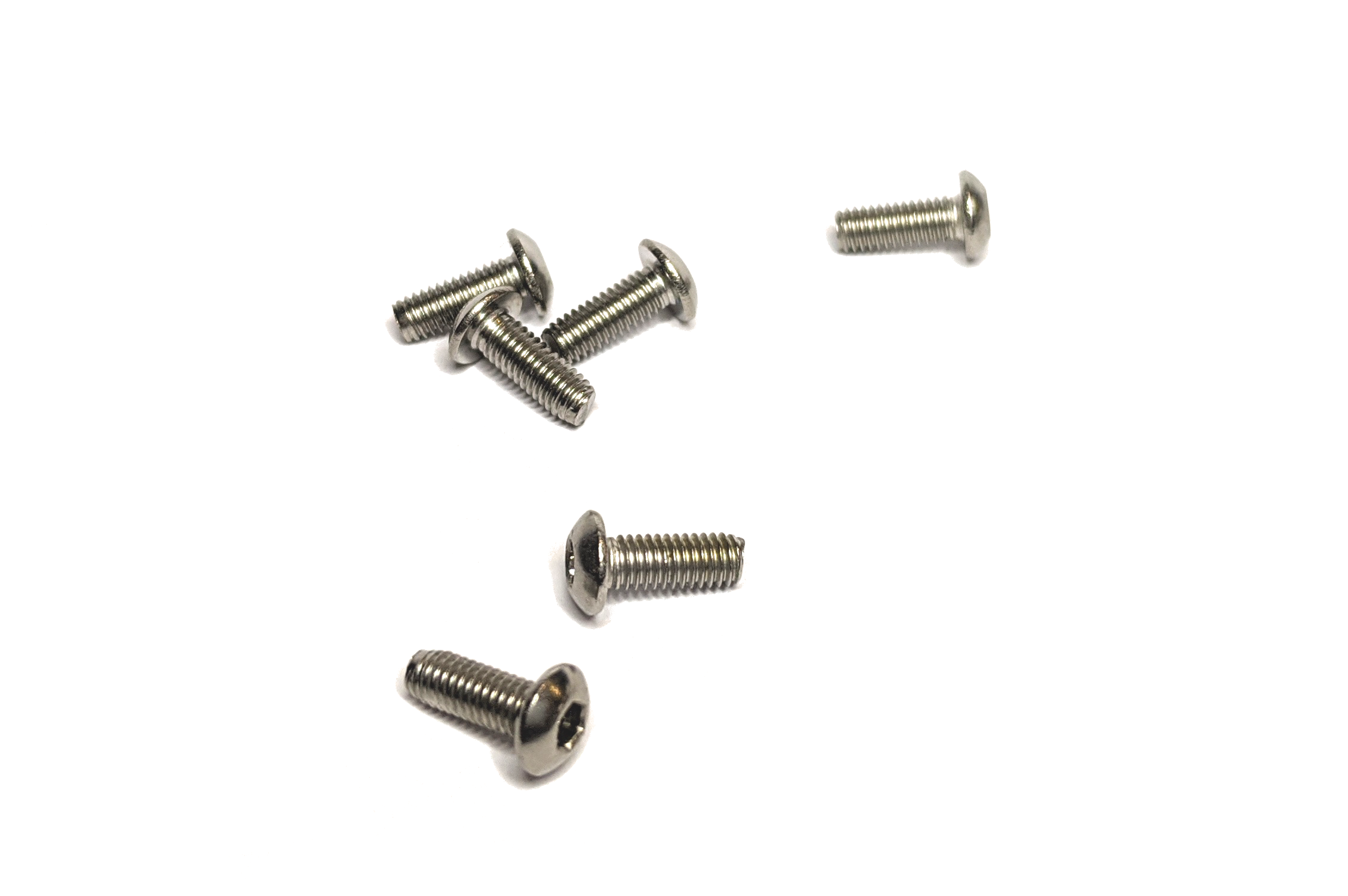
Around 50 M3x8 bolts
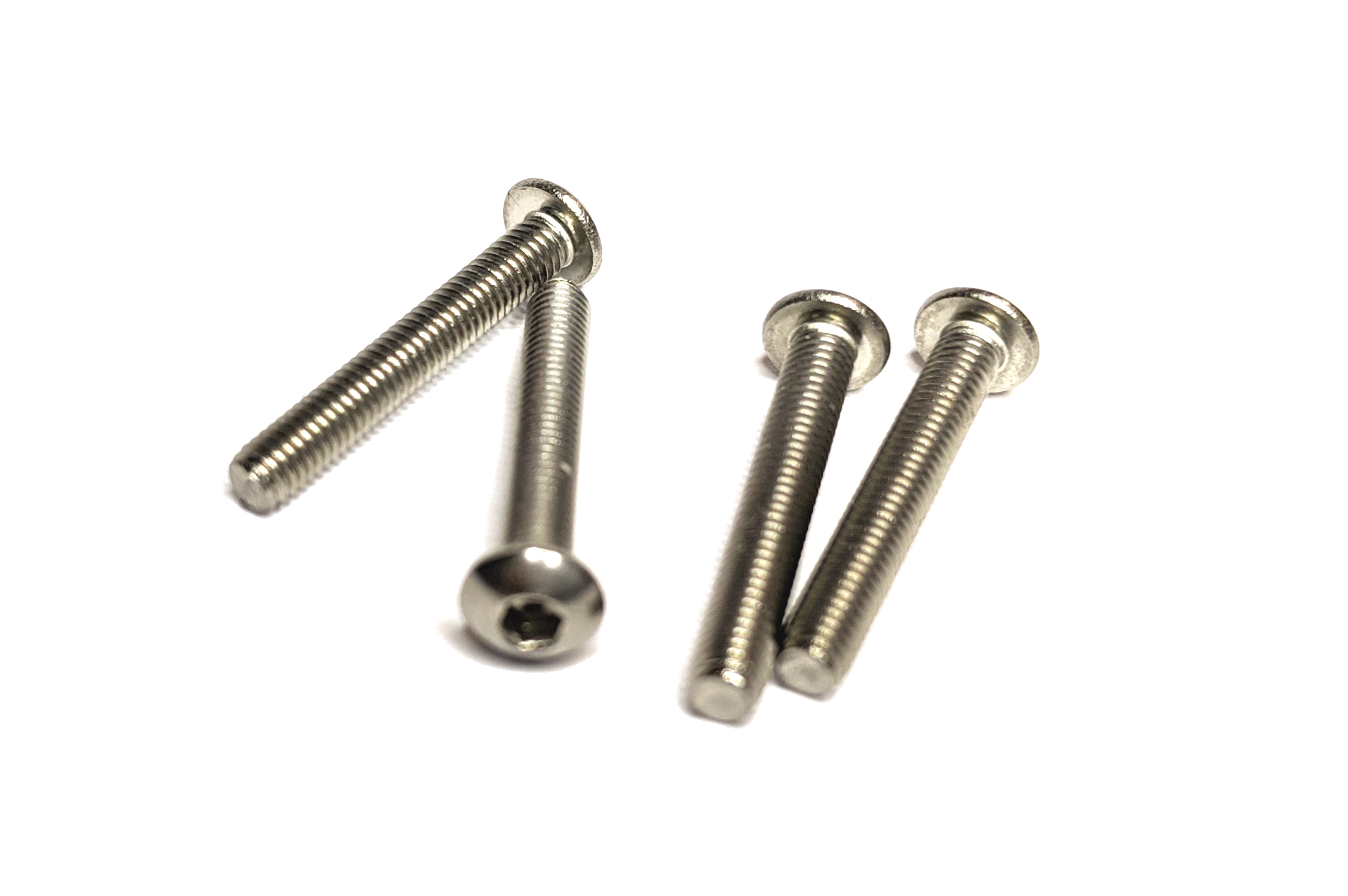
4x M3x20 bolts for the wheels
And here is a circuit overview of how the electronic components are connected
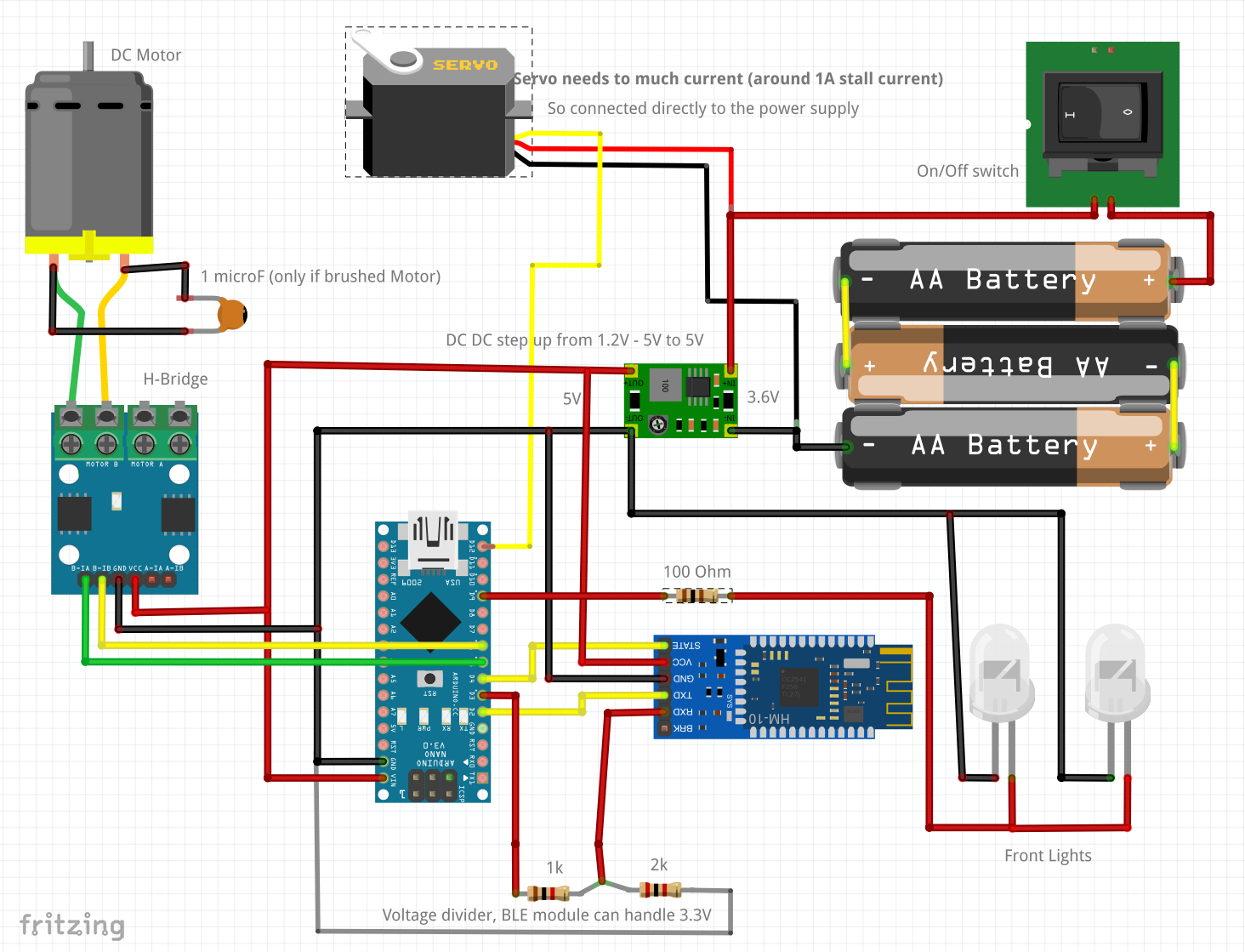
Arduino nano uses a Mini-B USB connector, so You will also need one of these. Some mobile phones used them back in the day, but they never got very popular. If You don’t have one from your old smartphone, check if You can get one packed together with the Arduino Nano module.
What’s next?
In the next blog posts (and videos) I will explain step by step in detail how I build the car. I will try to make it as simple as possible, so every one of You can build one. I will also explain the logic after every step, so this is also a great project for beginners that want to learn some electronics and applied programming.
There will be also a separate blog post (and video) for the people that just want to build the car as fast as possible and don’t need (or want) extra explanations about how it really works.
Next: BlueCArd part 2 – What is a breadboard and how to use it


Leave a Reply
You must be logged in to post a comment.