


The number of digital pins on a microcontroller seems to never be enough, but with shift registers, You can get as many new pins as you like!

For my next project, I need WiFi and decided to use NodeMCU. The problem is that it has even fewer usable digital pins than the Arduino Nano.
I also need to control four stepper motors, four IR sensors, and a real-time clock. Only for the steppers, I need sixteen pins!
Using only the NodeMCU would be impossible, but here the shift register 74HC595 comes to help.
How to use the 74HC595 shift register
Pins
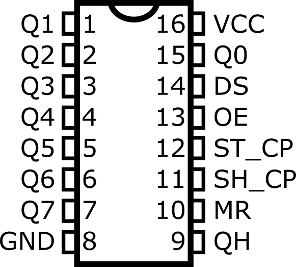
- Q0 to Q7 are the eight output pins
- GND and VCC are for the power supply
- MR is the master reset pin (active is low)
- SH_CP is the clock pin
- ST_CP is the latch pin
- OE is the output enable pin (enable is low)
- DS is the data pin
- QH is the serial out to cascade another shift register
To save some pins on the NodeMCU I will hardwire the MR pin to HIGH (don’t reset) and the OE pin to LOW (output enabled).
In this way we need only three pins from the NodeMCU to control the 74HC595 shift register:
- The data pin (it will shift the data into the register bit by bit)
- The clock pin
- The latch pin
We will get eight pins from the shift register (five pins total gain). But we can just connect another shift register to the QH pin and get another eight pins for free!
In general, I will use the register like this:
- Set latch pin to LOW (disable data pins change)
- Shift the data to the registers. For this, I’ll use the built-in shiftOut() function.
- Set latch pin to HIGH (change all data pins to the values set in step 2)
The shiftOut() function automatically sets the clock pin to HIGH and LOW to shift bitwise one whole byte to the shift register. If there are multiple registers connected then the first byte goes to the last register (the data is shifted from one register to the next).
A simple LED circuit to test programming the shift registers
To test programming the shift registers I build this simple circuit with two shift registers connected in serial:
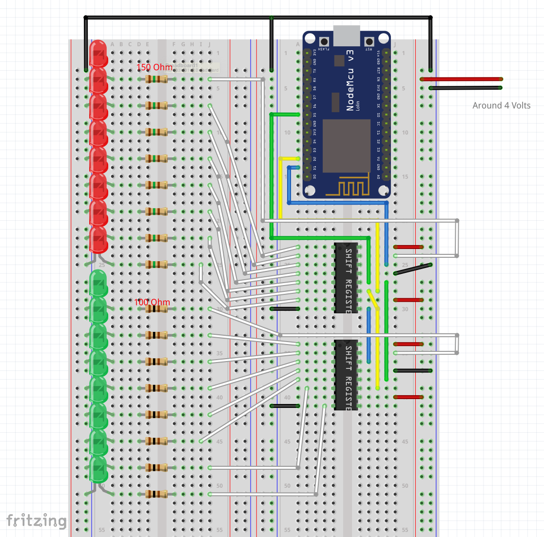
NodeMCU is powered by USB. The shift registers and the LEDs are using an external power supply (around 4V). The problem here is that the NodeMCU pins have 3.3V and the shift registers need 5V. If I power the shift registers (and the LEDs) with 5V the 3.3V from the NodeMCU is not enough, so we need to go lower.
This problem can be easily resolved using a logic level shifter (see below).
Wiring:
- D1 pin is used as the Data pin (connected to pin 14 on the shift register 1) – blue wire
- D2 pin is used as the Clock pin (connected to pin 11 on the shift registers 1 & 2) – yellow wire
- D5 pin is used as the Latch pin (connected to pin 12 on the shift registers 1 & 2) – green wire
- The QH pin of the first shift register is used as a data pin of the second register
- VCC and GND of both shift registers are connected to the power supply
- Pin 13 of both shift registers is connected to Ground (output always enabled)
- Pin 10 of both shift registers is connected to VCC (no reset)
- Pins Q0 to Q7 are connected to the LEDs (shift register 1 to the red LEDs and shift register 2 to the green LEDs)
Now comes the fun part!
Programming the LEDs to blink in different patterns
A short video demonstrating the LEDs in action:

The sketch code can be found on GitHub: https://github.com/nenovmy/arduino/tree/master/leds_disco
To be able to program the LEDs freely I created an array for the individual bits:
1 | byte bits [16]; |
Now all I have to do is set these “bits” as I wish (almost like normal digital output pins).
To shift the bits to the shift registers I have to convert them first to bytes. For this I wrote two functions for the first and the second byte:
1 2 3 4 5 6 7 8 9 10 11 12 13 14 15 | int bitsToB1() { int b = 0; for(int i=0; i<8; i++) b |= bits[i] << i; return b; } int bitsToB2() { int b = 0; for(int i=0; i<8; i++) b |= bits[i+8] << i; return b; } |
Now I can use these functions to send the data to the shift registers:
1 2 3 4 5 6 7 8 9 10 11 12 13 14 | void writeData() { int data1 = bitsToB2(); int data2 = bitsToB1(); // disable LED update digitalWrite(latchPin, LOW); // shift out the data (second shift register must be send first) shiftOut(dataPin, clockPin, MSBFIRST, data1); shiftOut(dataPin, clockPin, MSBFIRST, data2); // update the LEDs digitalWrite(latchPin, HIGH); } |
With this function, I can use the shift register pins almost exactly as the normal digital pins.
To test how this all works I wrote three LED animation functions. You can find them in the code.
Controlling four stepper motors
Now that we know how to use the shift registers controlling multiple stepper motors is pretty easy.
The stepper driver boards need 5V input, so now I decided to use a logic level converter.
Here is the circuit:
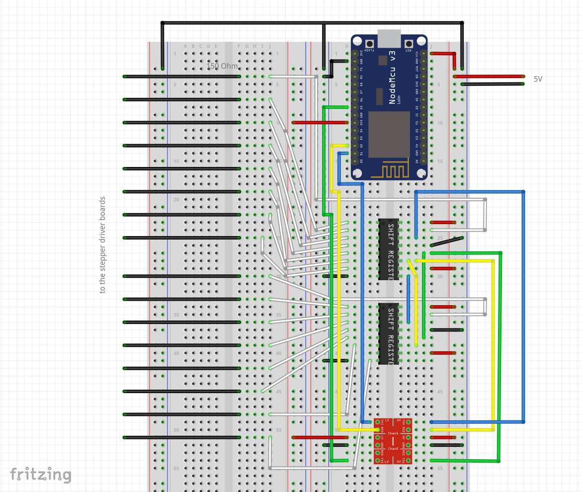
The stepper driver board needs 5V digital input, so we have to use a logic-level converter. We can connect the low voltage of the logic level converter to the 3.3V output of the NodeMCU and the high voltage to the 5V of the power source.
Now we can connect the three jumper cables from the NodeMCU to the logic level converter first and then to the shift registers.
We are using now 5V input, so we can power up the NodeMCU with the 5V through the VIN pin.
The stepper motors can be powered up directly from the power source and the shift register output pins can be used to control them (4 motors x 4 wires)
I had to make a minor modification of my stepper motor class, so it doesn’t write directly to the digital pins, but to an array that later can be sent to the shift registers.
The sketch code can be found on GitHub: https://github.com/nenovmy/arduino/tree/master/control_stepper_motors_with_shift_registers
Here is a demo video of how everything works:
I chose to use a NodeMCU because of the WiFi capabilities. In the next tutorial, I’ll show you how to use the WiFI of the NodeMCU.


Leave a Reply
You must be logged in to post a comment.