


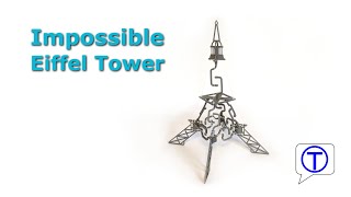
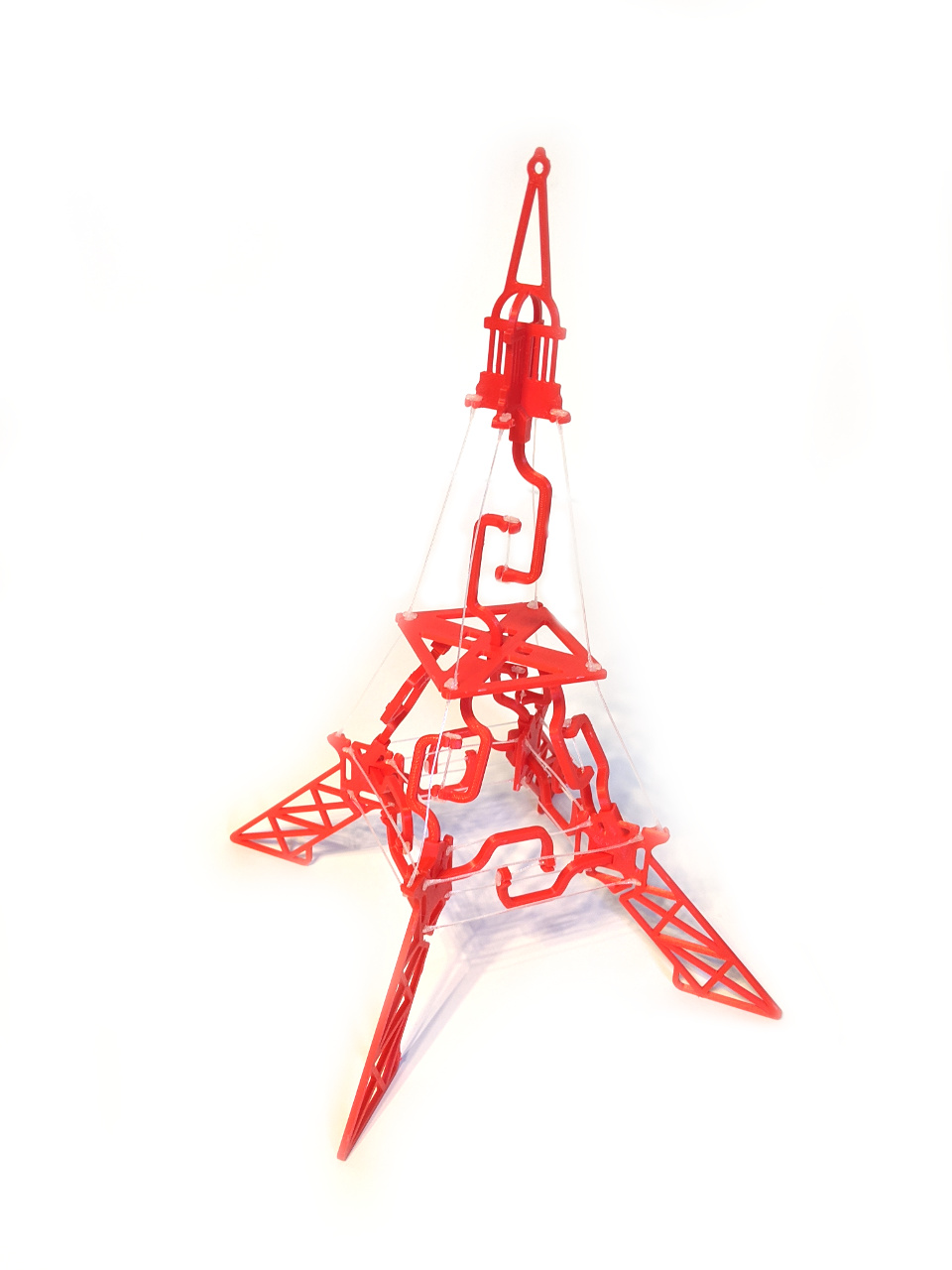
How to build your own impossible Eiffel tower – a fully 3D printed tensegrity structure in a gift-card format.

I am fascinated by the tensegrity (tension & integrity) buildings and structures. They look as if they are kept together by magic defying the laws of nature.
Of course, I wanted to design my own tensegrity structure and in the end, I decided to design something a little bit more complex – The Impossible Eiffel Tower.
I assembled multiple different tensegrity structures and the hardest part was always cutting the strings to the right length and binding them. Even for the simplest structures, I needed a lot of time to make them work.
To address this problem, I decided to design 3D printable strings and make the assembly as simple as possible.
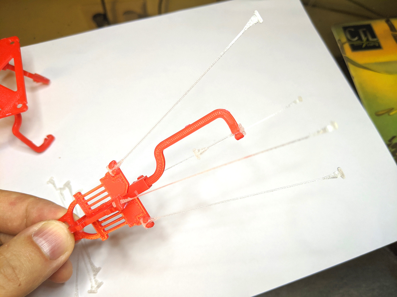
The impossible Eiffel Tower is a fully 3D printable model!
If You wish, you can still use your own strings though, although I don’t recommend it!
If you don’t trust the 3D-printed strings, here is a video that may convince you:
Thingiverse: https://www.thingiverse.com/thing:4530870
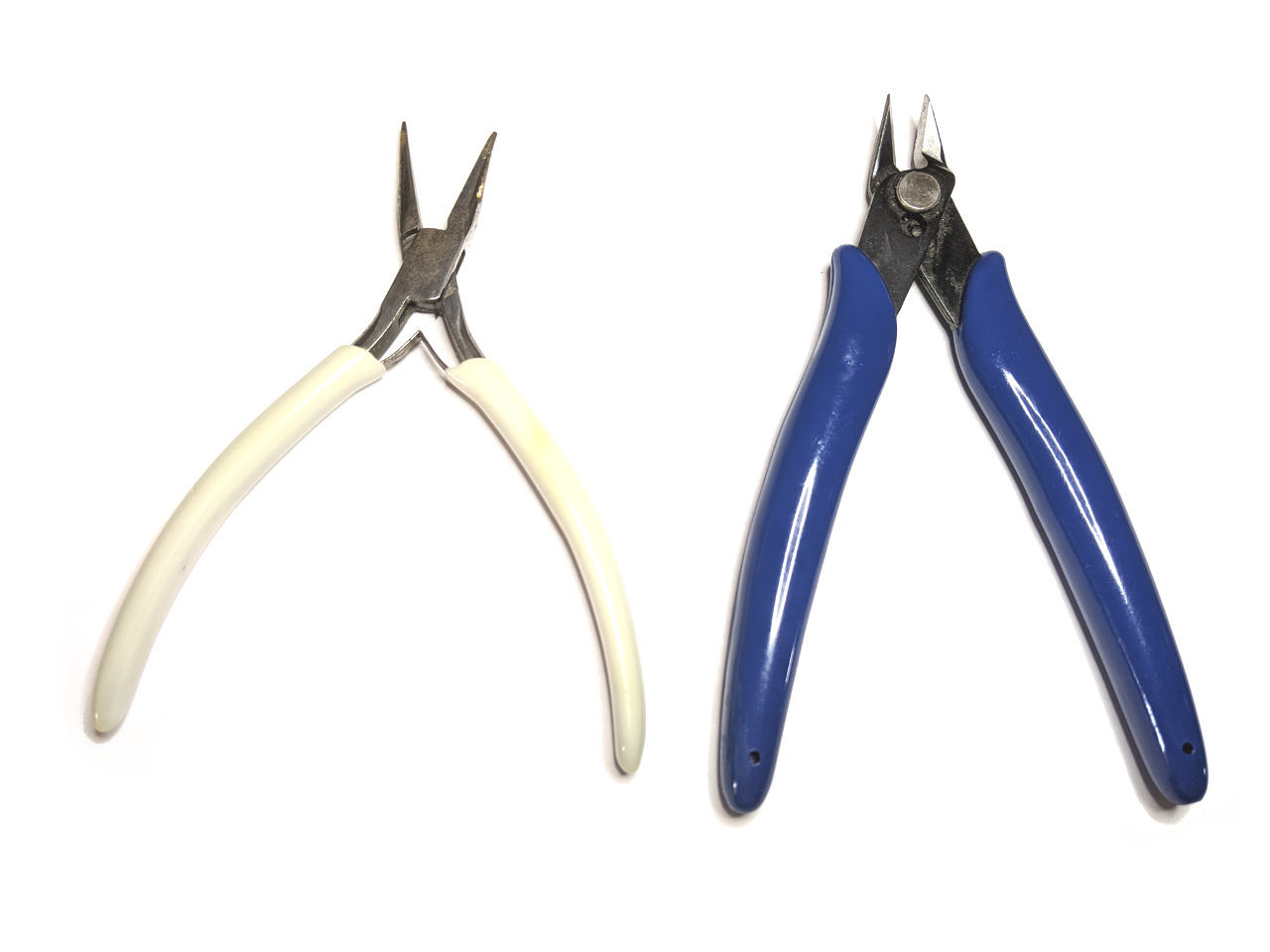
Tools to use
I recommend these tools for the assembly:
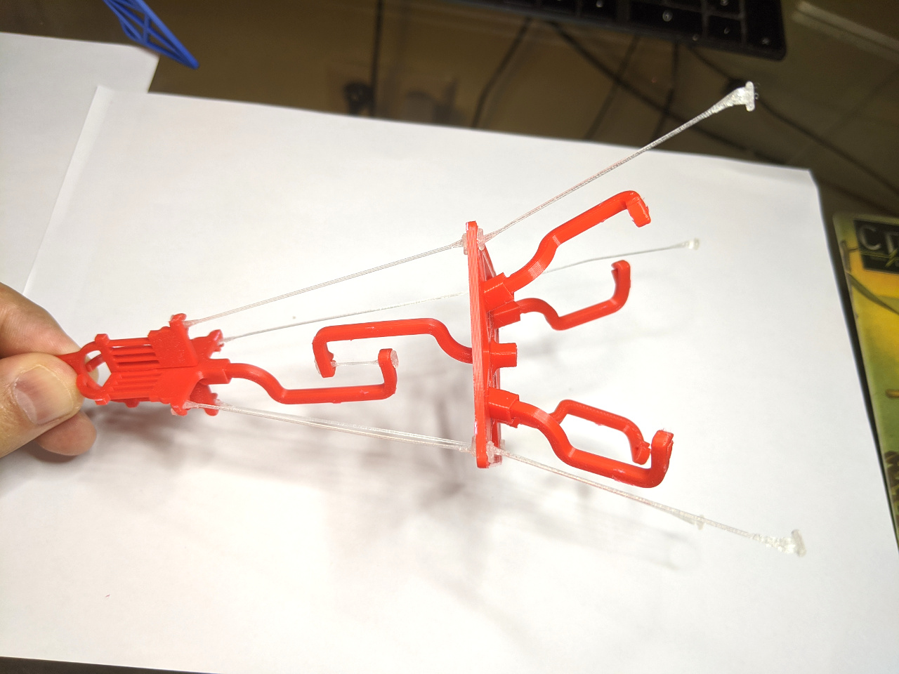
Preparing the parts
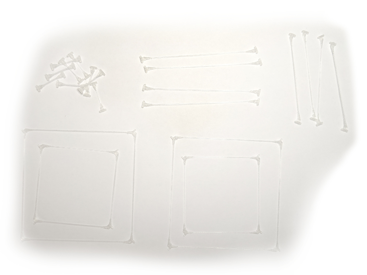
I designed The Impossible Eiffel Tower as a gift card in A5 size.
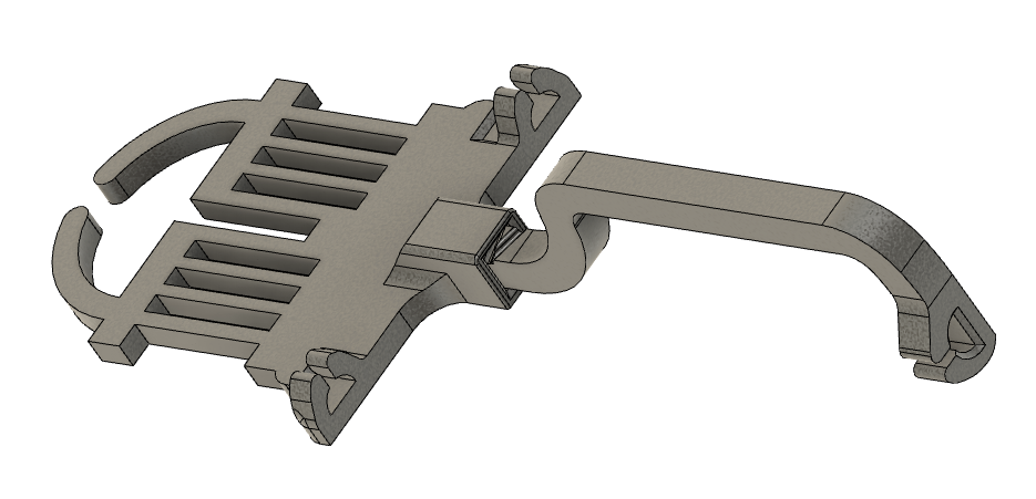
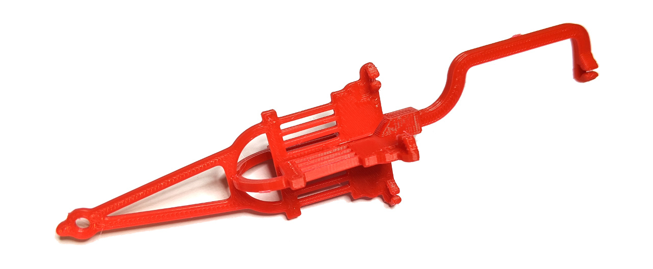
 - 3D printed parts (right)")
1. cut all the elements from the gift card (be careful not to damage the elements).
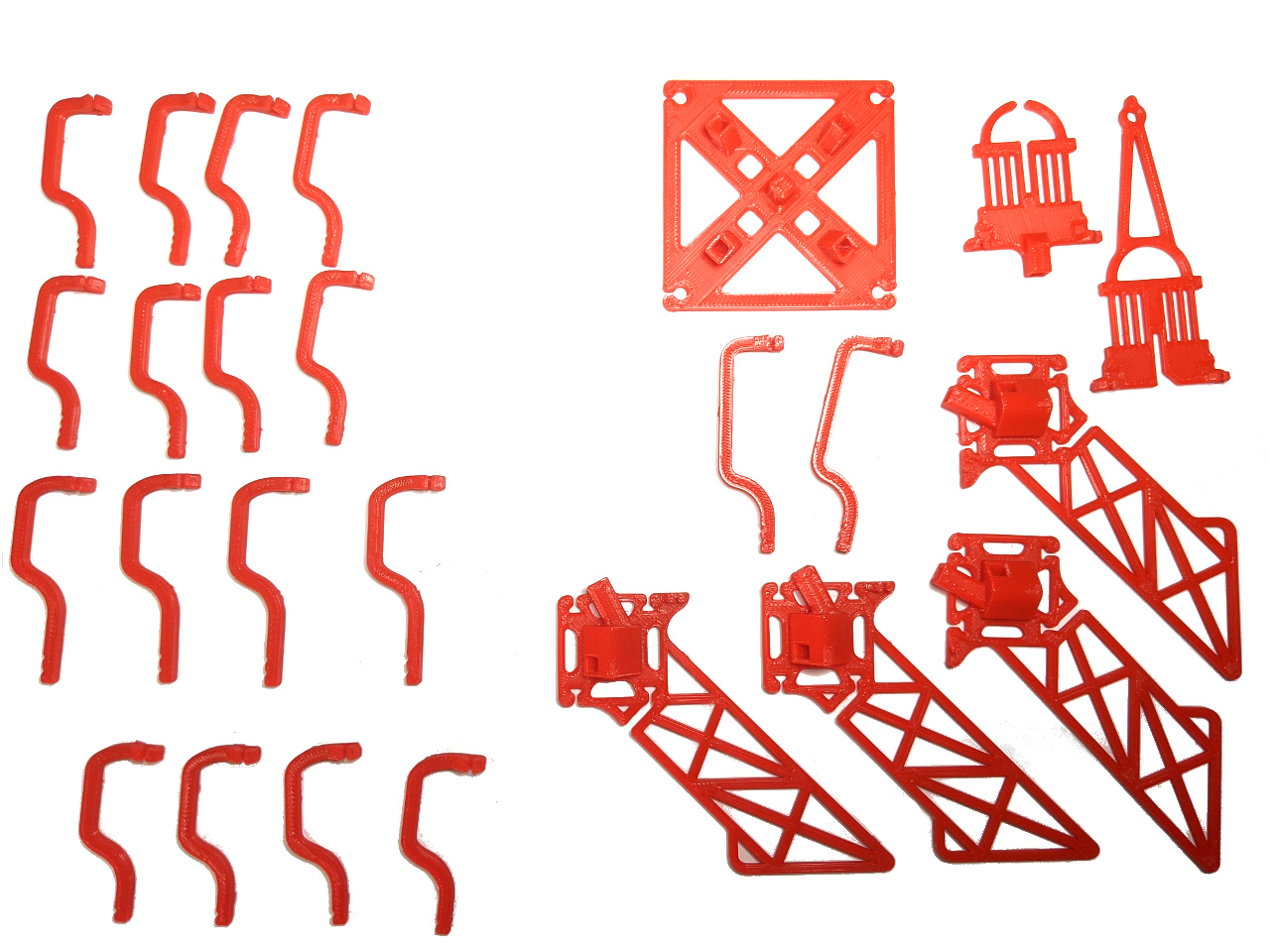
List of elements:
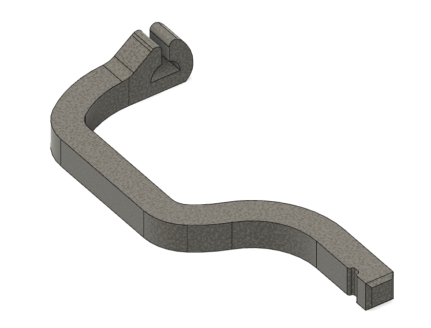
4x connectors type I
(C1)
4x connectors type II
(C2)
8x connectors type III
(C3)
2x connectors type IV
(C4)
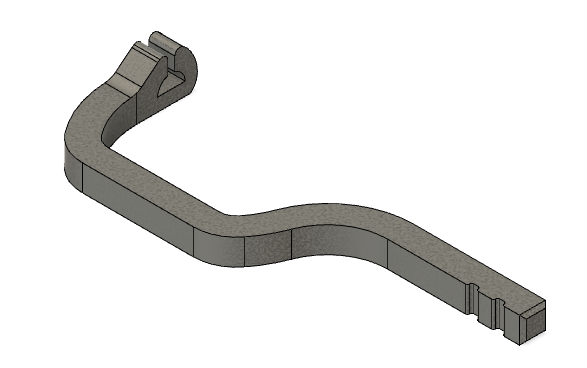
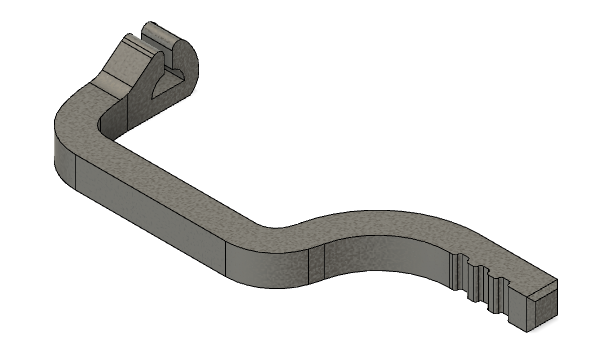
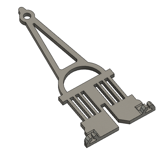
2x feet type *
(F1)
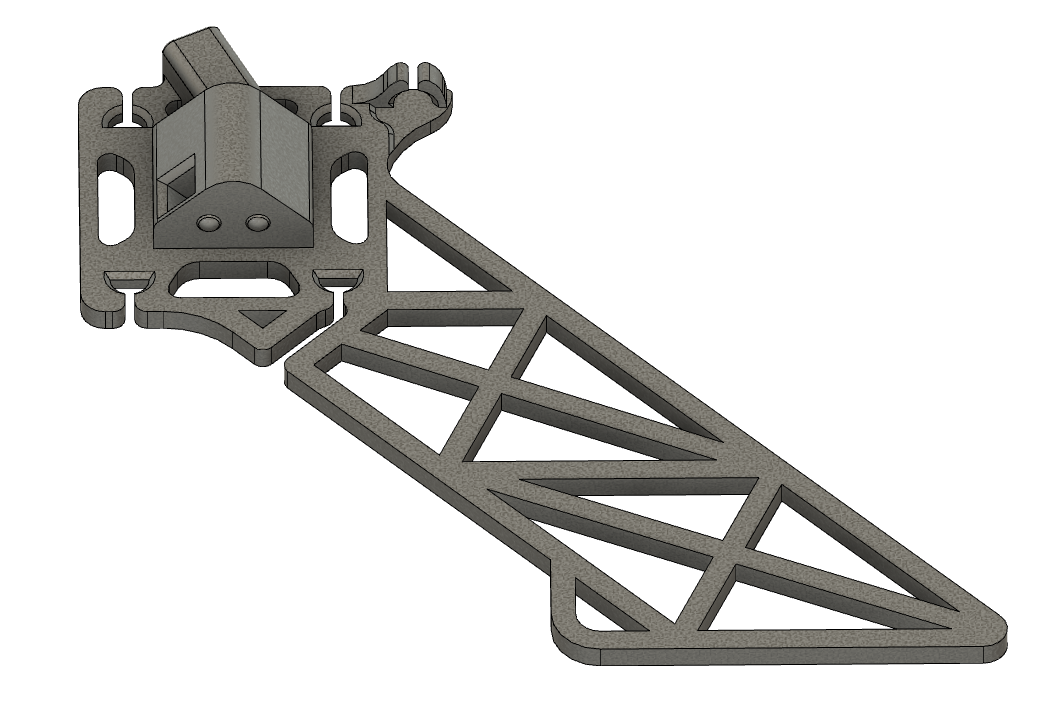
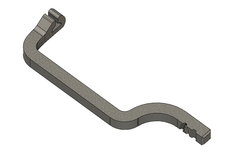
2x feet type **
(F2)
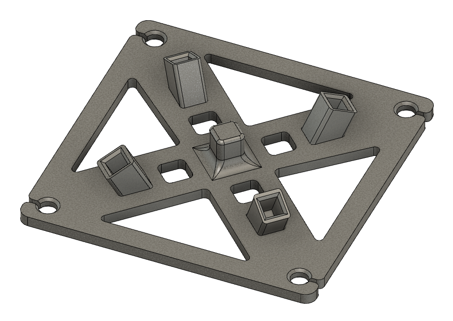
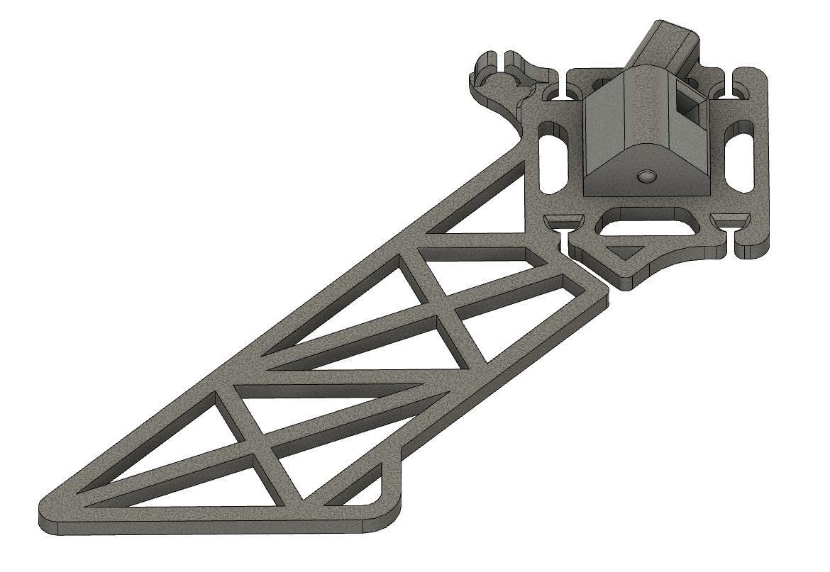
1x base
(B)
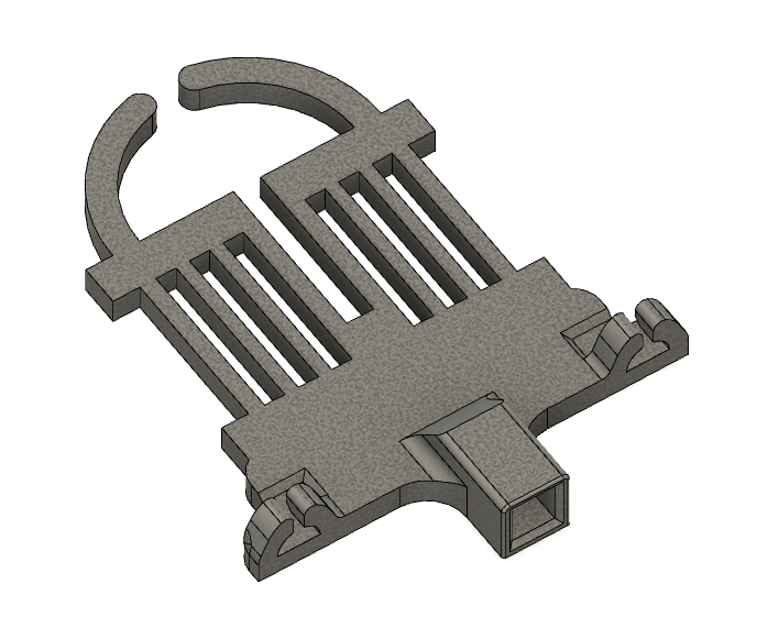
1x top short
(TS)
1x top long
(TL)
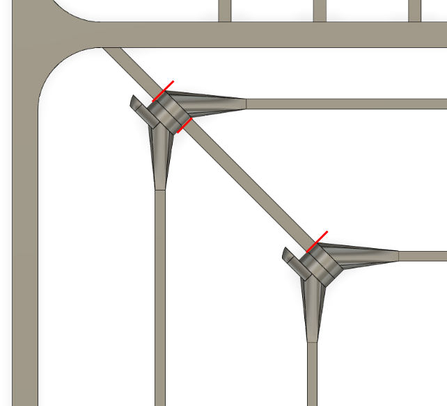
2. Cut the strings
WARNING!!! Be very cautious and cut the strings out without damaging them. Cut the loop strings at the red lines shown below:
Used strings:
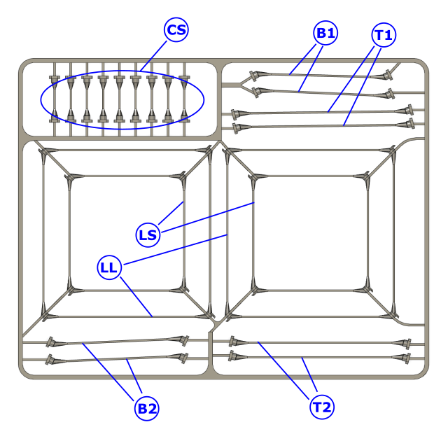
- 2x Loop Strings – Short (LS) – inner feet strings
- 2x Loop Strings – Long (LL) – outer feet strings
- 9x Connector Strings (CS) – strings between connector1
- 2x Base strings type 1 (B1) – strings between the feet and the base
- 2x Base strings type 2 (B2) – strings between the feet and the base
- 2x Top strings type 1 (T1) – strings between the base and the top
- 2x Top strings type 2 (T2) – strings between the base and the top
Assembly Manual
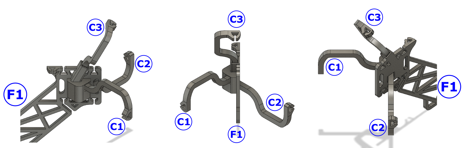
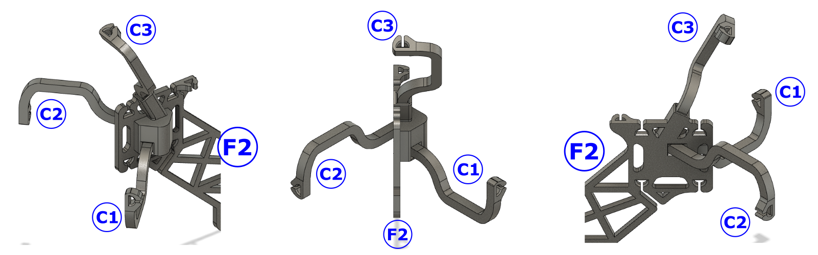
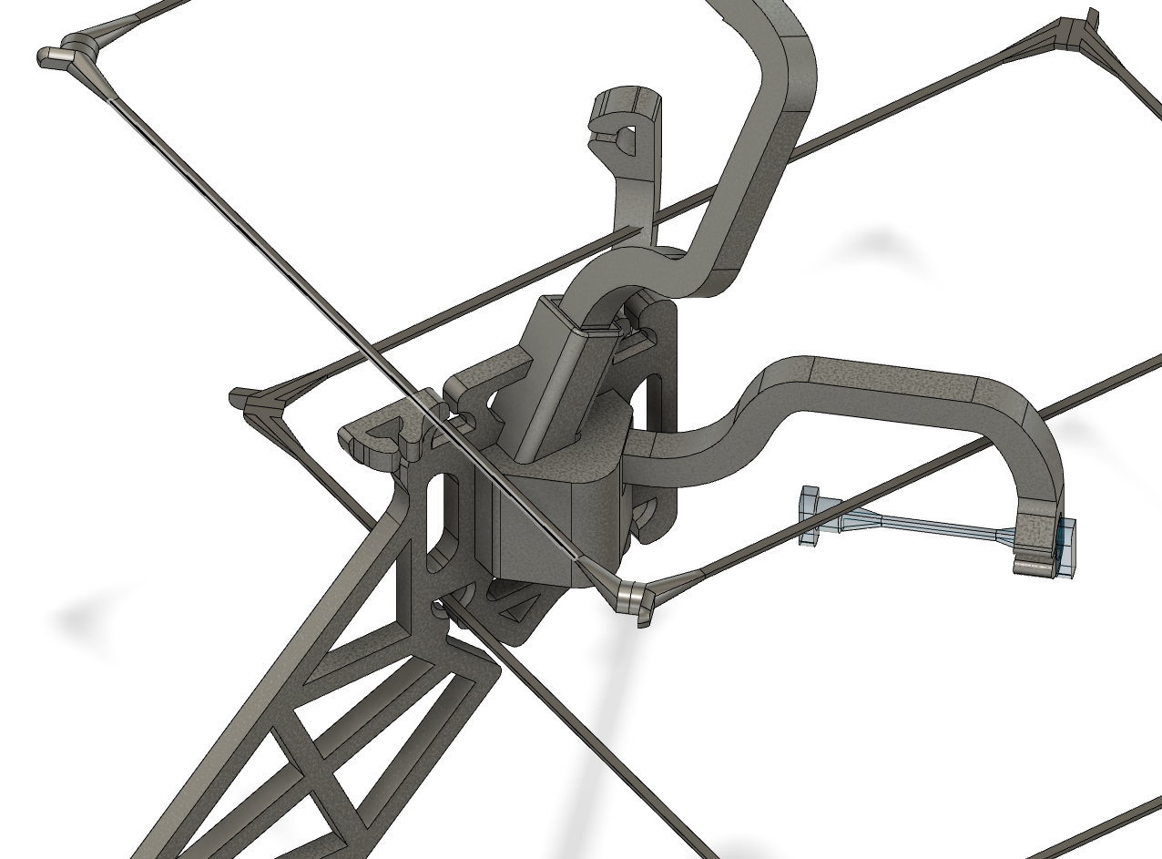
IMPORTANT: The orientation of the connectors should be exactly as shown in the image below!
Step 1
Insert connectors C1, C2, and C3 into the foot F1:
Repeat for the other F1 element.
Insert connectors C1, C2, and C3 into the foot F2:
Repeat for the other F2.
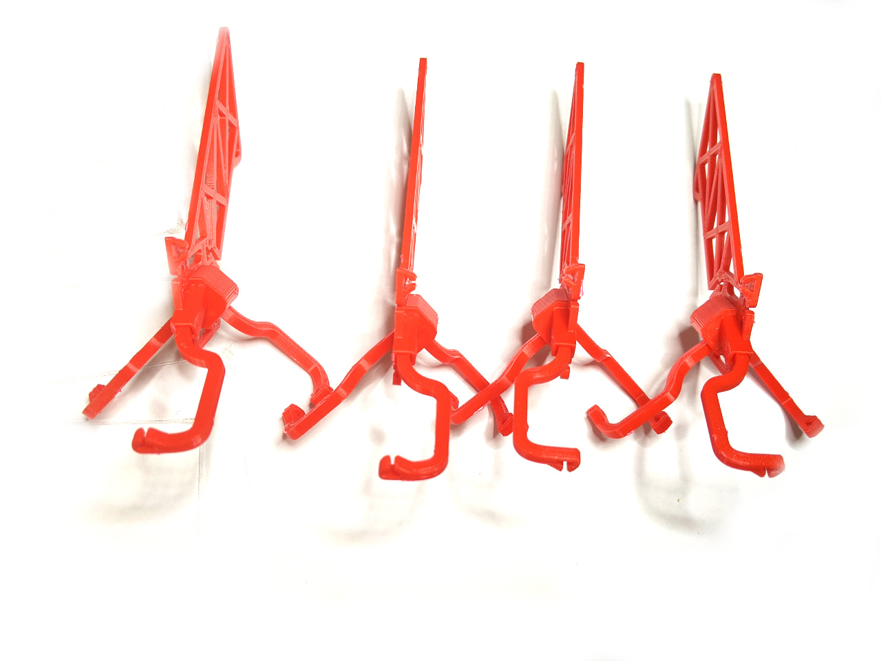
You should have now four assembled feet:
Step 2
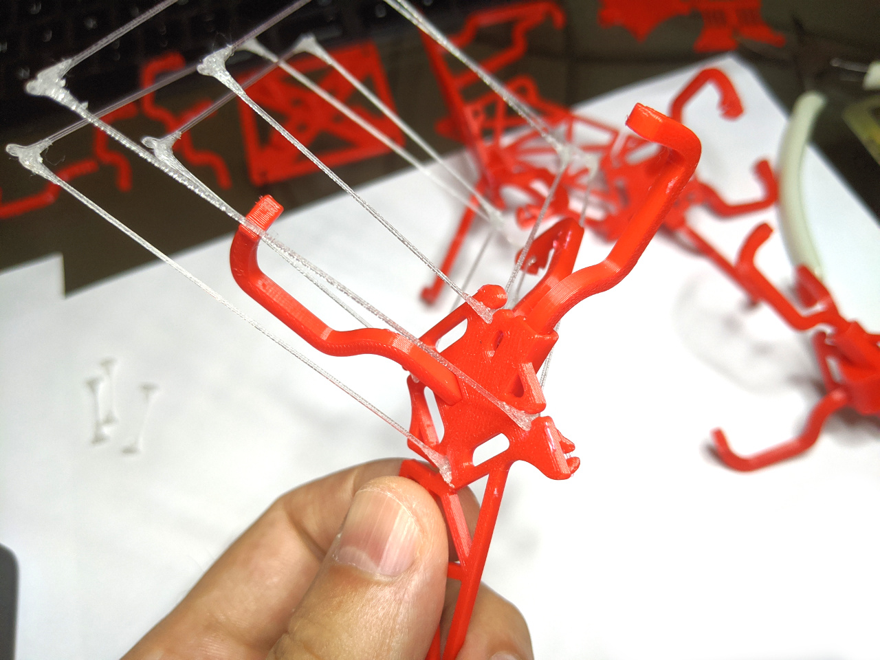
Insert a connector string (CS) in the connector (C1) of an F1 foot element:
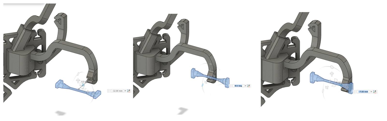
TIP: use this technique every time when You connect a string.
Add the loop strings LS and LL to F1:
IMPORTANT: You have to insert the top loops from right to left and the bottom loops from left to right. Be aware of the hole form and the string connector form at the corners (half cylinders)!
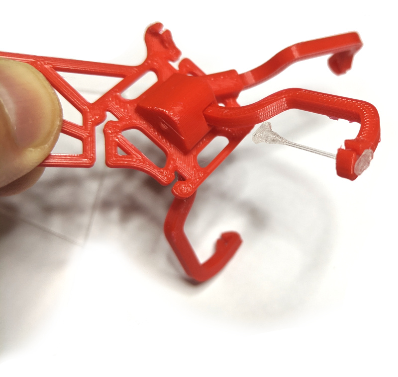
After you insert the strings the F1 should look like this:
Take one F2 element and connect the C1 connector to the CS string.
Attach then the loop strings:
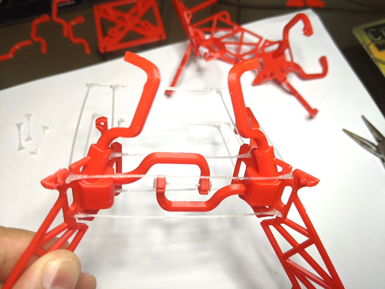
Repeat for the rest of the feet:
Step 3
Insert connector C4 into the top short element (TS):
Insert the top short element (TS) into the top long element (TL):
Step 4
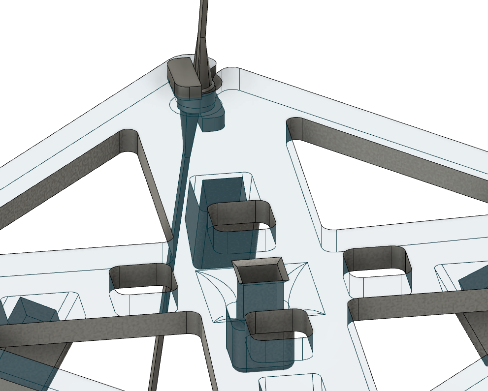
Insert the connector C4 and the rest of the C3 connectors into the base (B):
Step 5
Insert a connector string (CS) into the C4 connector (attached to the top element).
Insert top strings (T1s and T2s) into the top elements (TL and TS):
IMPORTANT: the strings are angled! Compare it with the image below.
Step 6
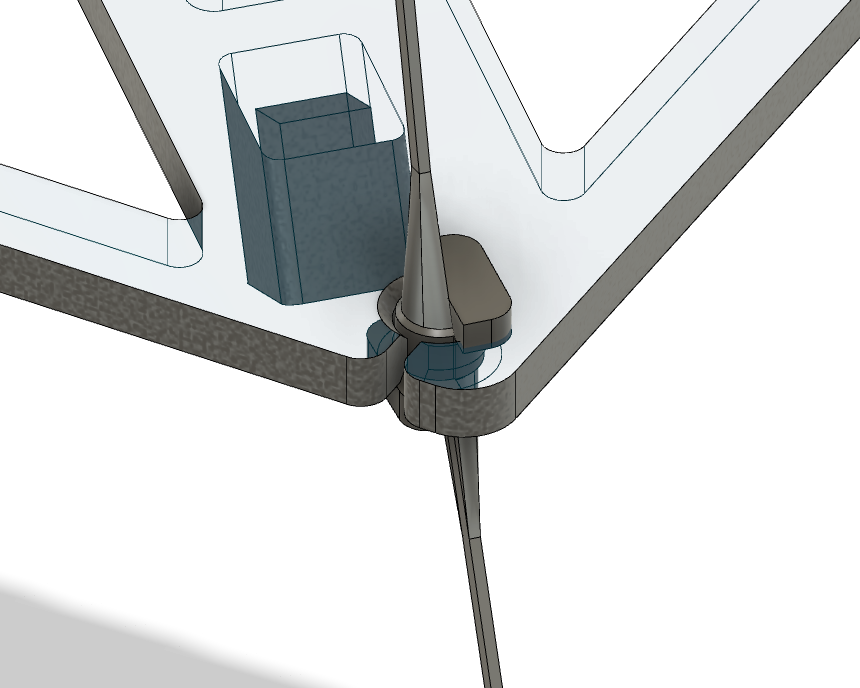
Attach the top assembly to the base and insert the base strings.
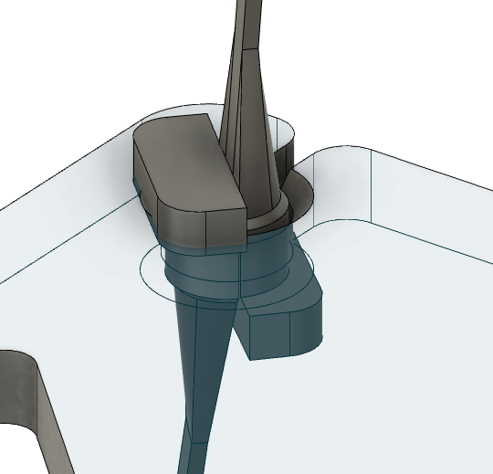
IMPORTANT: When the top strings and the base strings are attached to the base they must form a whole cylinder as shown in the images below:
Now the top assembly should look like this:
Step 7
Insert the remaining four connector strings (CS) into the C3 connectors of the bottom assembly.
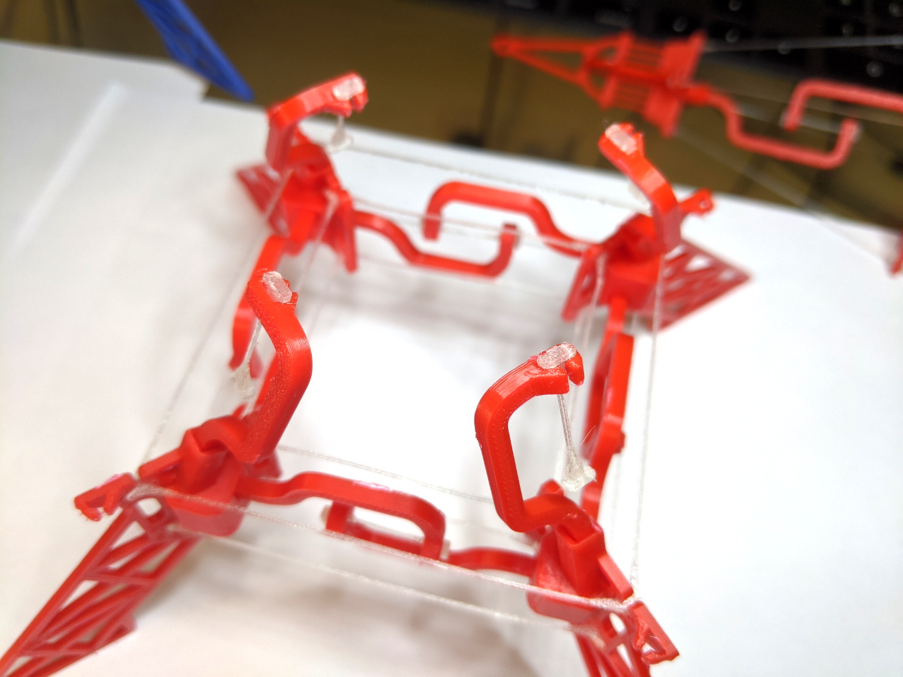
Now attach the top C3 connectors of the top assembly to the CS strings.
Important: rotate the top assembly around its vertical axis until all C3 connector of the top assembly faces the same direction as the C3 connectors of the bottom assembly.
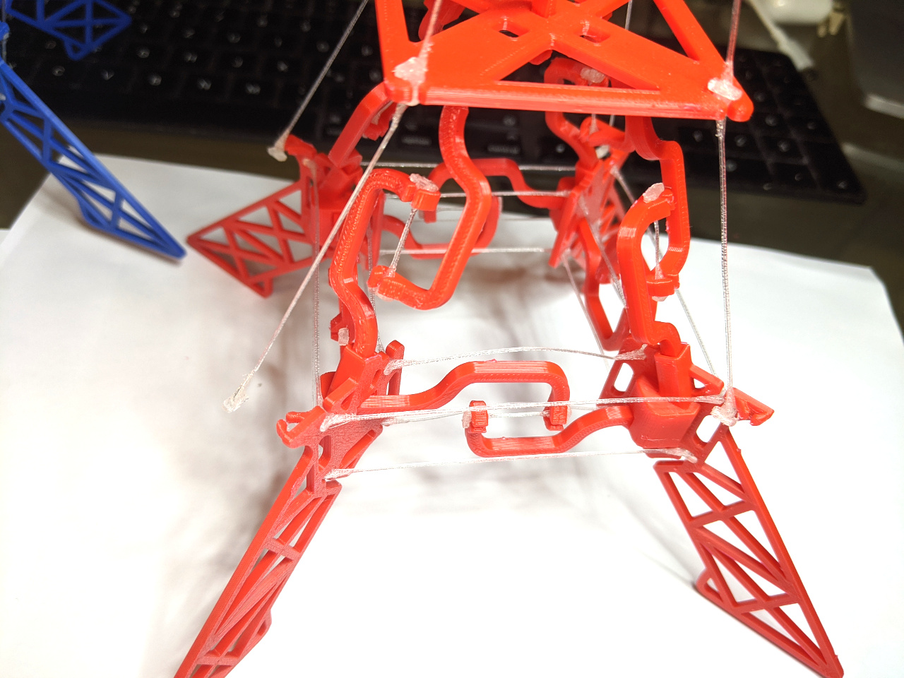
Step 8
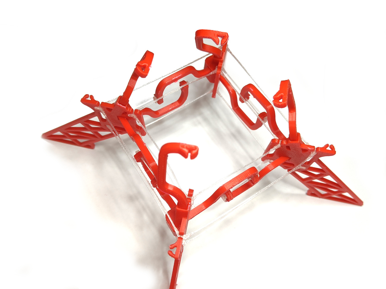
Attach the base strings (B1s and B2s) to the feet.
The impossible Eiffel Tower is ready!
Enjoy!
If you like The Impossible Eiffel Tower check also my other projects: https://www.thinker-talk.com/
Don’t forget to check my YouTube channel: https://www.youtube.com/user/maylow99/videos


Leave a Reply
You must be logged in to post a comment.