


To power the Arduino Board and the rest of the electronics we need a stable power source. In this tutorial, I’ll show you what is a DC-DC Boost Converter (aka step-up converter), how to use it, and why we need it

The elements used in this tutorial are from the list of elements needed for BlueCArd. The detailed list can be found here:
The elements needed for this tutorial are:
The elements from the last tutorial (without the USB cable): Arduino Nano First Steps
- 1x DC DC Boost Converter -> from 1V – 5V to 5V and at least up to 500 mA
- 4x more pin connector cables (2x black and 2x red)
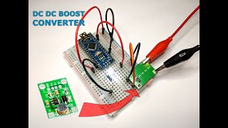
I also made a video where I show how to connect the circuit and how the used current changes when we change the input voltage. You can watch the video here:
What is a DC-DC Boost Converter?
A boost converter (step-up converter) is a device that can increase the voltage from the power source (while decreasing the current).
For BlueCArd I used this one:

As you can see You can put any voltage between 1V and 5V at its input and it will output a stable 5V.
How does it work (very short explanation)?
I’m not an electrical engineer and I’ll try to explain it to the extent of my understanding. If you find any errors please send me a message or write them in the comments, so I can fix them. Thank You!
Below is the general circuit of a DC-DC boost Converter:

Vin is the input voltage (in our case from 1V to 5V)
- Vout is the output voltage (in our case 5V)
How it works:
- When switch S is closed the current follows the blue line and the inductor L creates a magnetic field.
- When switch S is opened the magnetic field of the inductor L starts to collapse inducing current through inductor L and creating a high-voltage spike. The current is pushed through the red line (through the diode D) and is stored in capacitor C.
- The diode D stops the current flowing back from the capacitor.
(Side note about capacitors: If you don’t know how a capacitor works -> the space between the plates indicates that the circuit is broken, the electrons can’t flow through -> the electrical particles are stored at the plates creating a load, and when the input voltage is lower than the capacitor tries to push the stored particles in the opposite direction -> that is why there is a diode there to stop the current flowing back.)
When the switch S is turned on and off very fast this effect pumps up the Vout. The switch S is normally a MOS transistor.
In this way, the Vout is much higher than Vin. But at the same time, the output current is much lower than the input current (P = U.I).
Why use the DC-DC Boost Converter?
The DC-DC Boost Converter has a 5V stable output independent of the power source.
- This means that I can power without a problem the Arduino Nano microcontroller and any other elements that require 5V
- I can also calculate the needed resistors for the LEDs and other components that need different voltages independent of the power supply and I don’t have to change the circuit when I change the power source
- I can also use e.g. only 1 rechargeable battery with 1.2V to power smaller circuits
Changing the circuit to use the DC-DC Boost Converter
Use the circuit from the last tutorial. To connect the step-up converter to the circuit do the following:
- Connect the 5V output of the boost converter to the (+) pins on the breadboard
- Connect the GND output of the boost converter to the (-) pins on the breadboard
- Connect the VIN pin of the Arduino Nano board to the (+) pins on the breadboard
- Connect one of the GND pins of the Arduino Nano board to the (-) pins on the breadboard
- Disconnect the USB cable (if you have it connected)
- Put some voltage (1V to 5V) on the input of the boost converter (GND or (-) on the IN- and (+) on the IN+)
- Enjoy
In the picture below I set up the input voltage to 3.6V (equals to 3 rechargeable AA batteries)

And on this picture, I changed it to 1.2V (equals to 1 rechargeable AA battery)
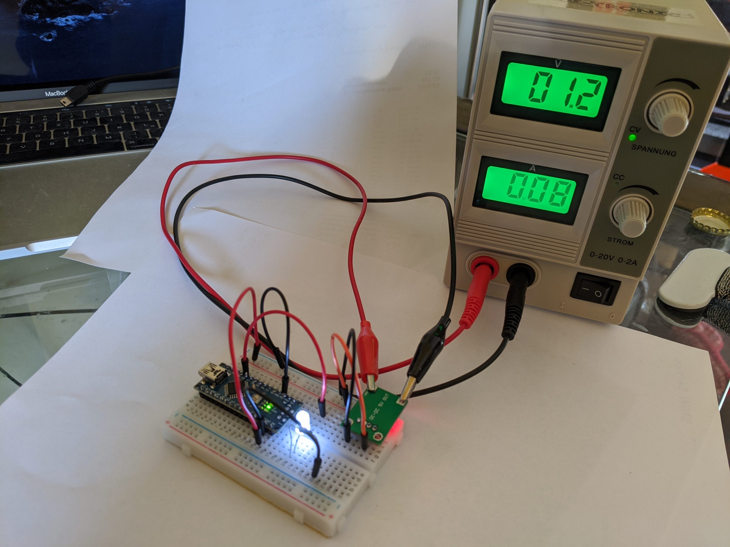
As you can see the circuit is working regardless of the input voltage. You can also see that the current flowing into the Boost Converter is different. Both times the power consumption is the same so when the voltage goes down the current must proportionally go up!
This is also why I decided to use 3xAA rechargeable batteries for BlueCArd, so I can limit the current through the Boost Converter.
Next Steps
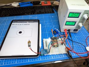
In the next tutorial, I’ll show you how to connect the AT-09 (HM-10) module to the Arduino Nano and how to send commands between the Arduino Nano and the BLE module.
Previous: BlueCArd part 3 – Arduino Nano first steps
Next: BlueCArd part 5 – Arduino Nano Bluetooth Module How To


Leave a Reply
You must be logged in to post a comment.