


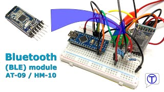
How to connect AT-09 / HM-10 Bluetooth Low Energy (BLE) module to the Arduino board and how to send data between the BLE module and the Arduino microcontroller.
 Module AT-09 / HM-10 to Arduino Nano")
The elements used in this tutorial are from the list of elements needed for BlueCArd. The detailed list can be found here:
I also made a video on how to connect and use the BLE module. You can watch the video here:
To communicate with the mobile phone BlueCArd uses Bluetooth Low Energy (BLE). Arduino Nano doesn’t have an integrated Bluetooth module, which is why an external one is needed. I used for BlueCArd the AT-09 module, which is fully compatible with the HM-10 module.
Needed Elements
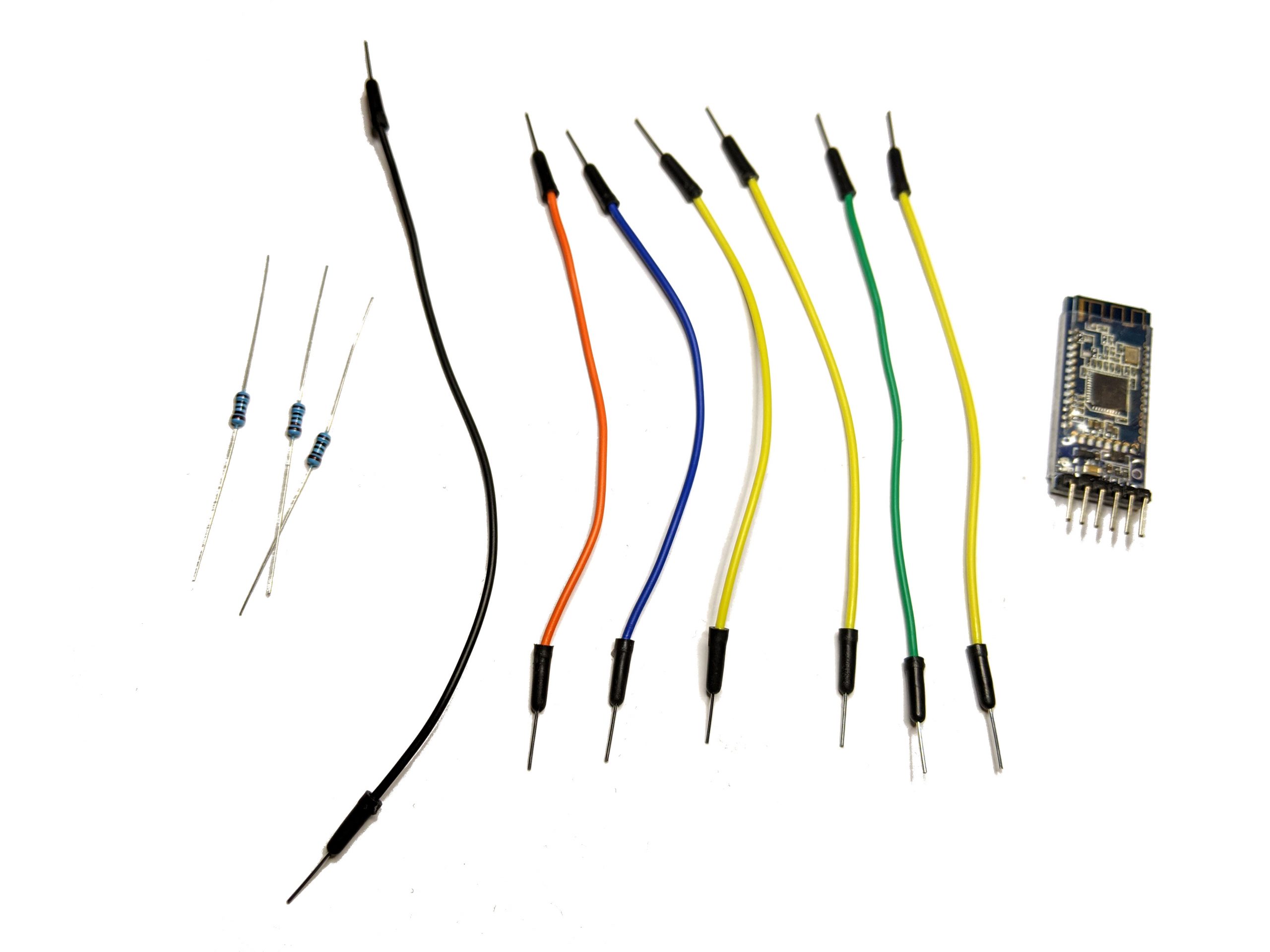
The elements needed for this tutorial are:
Reuse the board from the last tutorial: DC DC Boost Converter – what is it and why do we need it
For this tutorial we also need:
- 1x Bluetooth module (AT-09 or HM-10)
- 7x pin connector cables
- 1x 1k resistor
- 1x 2k resistor (alternative 2x 1k resistors in series)
extra elements needed for this tutorial:
Short introduction of the AT-09 / HM-10 BLE Bluetooth module
The back side of the AT-09 / HM-10 looks like this:

We will use 5 of the six pins for the BlueCArd project.
- The module is powered through the VCC and GND. We will use the 5V output of the DC-DC boost converter to power the board.
- the RXD and TXD pins are used for serial communication with the Arduino board.
IMPORTANT: these pins require 3.3V, but the Arduino Nano digital pins have 5V.
There is no problem with the TXD pin because it just outputs to the Arduino and the 3.3V is enough to trigger the digital pins of the Arduino board.
For the RXD pin, we have to use a voltage divider. I’ll show you how to do that later.
- The state pin is used to determine if a Bluetooth device is connected. This pin will be used in later tutorials to power down the car when the connection to the Android phone is lost.
- UPDATE: I changed the code to use heartbeat from the Android phone instead of the STATE pin. The STATE pin is not needed anymore!
Plugging in the Bluetooth Module
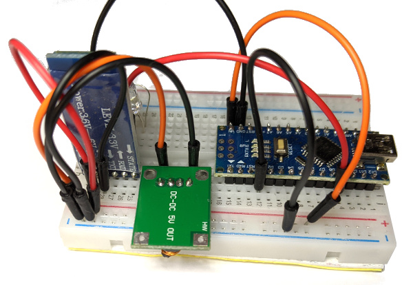
I rearranged the elements on the breadboard to have enough space to plug in the Bluetooth module:
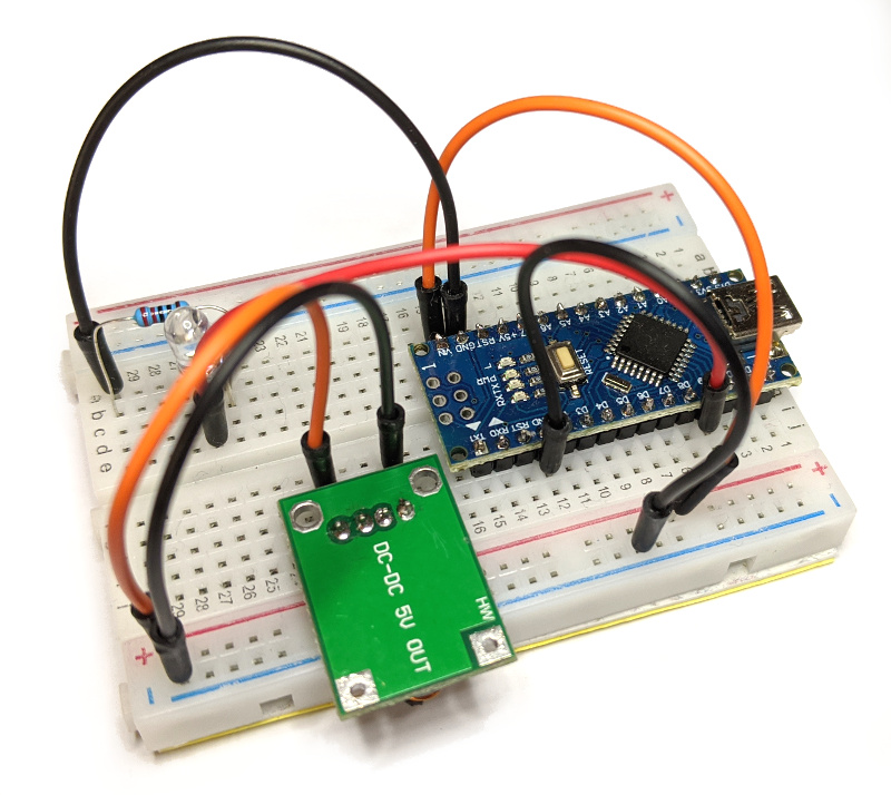
This is the exact same circuit as in the previous tutorial. All I did was rearrange the LED to the left side, so I have enough space for the BLE module on the right side.
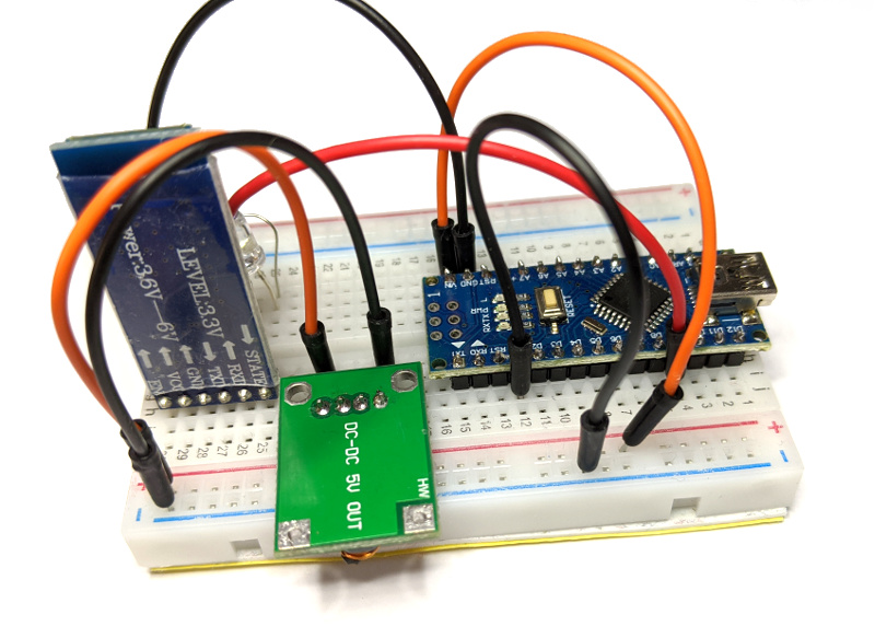
Now plug the Bluetooth module on the board like this:
- STATE pin of the BLE module in F25 on the breadboard
- EN pin of the BLE module in F30 on the breadboard
Now connect the VCC pin of the Bluetooth module to the (+) pins on the breadboard and the GND pin to the (-) pins on the breadboard.
Alternative for this tutorial you can power the Bluetooth module directly from the Arduino Nano board. To do this connect the VCC pin of the Bluetooth module to the 3.3V or the 5V pin on the Arduino Nano board and the GND pin to one of the GND pins on the Arduino board.
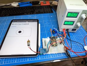
Now turn on the power (depending on the way You chose to power the BLE module, either connect the power supply to the DC-DC Boost Converter or plug in the USB cable to the Arduino Nano microcontroller)
The LED on the Bluetooth module should be blinking now.
Now you should be able to find the Bluetooth module with your phone. You don’t have to pair the BLE device with your phone. The good thing about BLE is that it doesn’t need pairing to work.
Connecting the Bluetooth module to the Arduino Nano microcontroller
Until now we have plugged the Bluetooth module into the breadboard and connected it to the power supply. To enable the Arduino to communicate with the Bluetooth module we have to connect the TXD and RXD pins of the Bluetooth module to some digital pins of the Arduino (also the STATE pin). For this, we can use any digital pins >= D2 on the Arduino Nano board.
For the RXD pin, we have to use a voltage divider like in the circuit below.
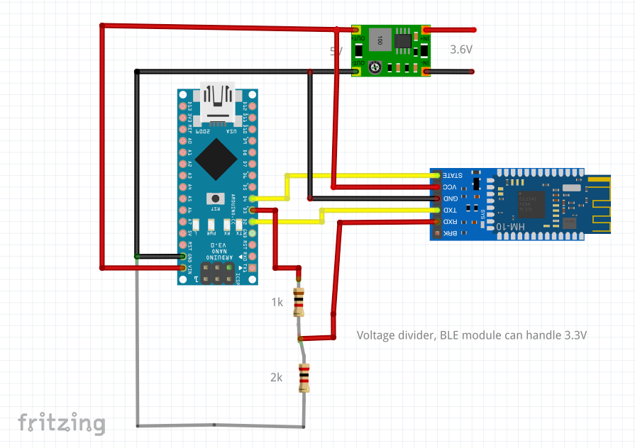
I don’t have a 2k resistor on hand, so I used 2x 1k in serial. I connected the circuit on the breadboard like this:
- connect the STATE pin to D4
- connect the TXD pin to D2
- connect the first 1k resistor to e21 and c22 on the breadboard
- connect the second 1k resistor to d22 and b23 on the breadboard
- connect the third 1k resistor to c23 and a24 on the breadboard
- connect a pin connector cable to e24 on the breadboard and the (-) pins (or to one of the GND pins on the Arduino Nano)
- connect a pin connector cable to c21 on the breadboard and the D3 pin of the Arduino Nano board
- connect a pin connector cable to a22 on the breadboard and the RXD pin on the Bluetooth module
It should look like this:

Now you can connect the Arduino board to the computer (with the USB cable).
With this, the hardware part of this tutorial is over.
Testing the connection and configuring the Bluetooth module
Here starts the software part of this tutorial. Before we start writing code, we need some background information about the Bluetooth module and the communication between the elements.
AT Commands
The Bluetooth module is configured with AT commands (AT stands for Attention). AT commands are used for controlling modems. These are simple commands that have the following format: “AT” + “NAME” + “VALUE”.
We can send AT commands to the Bluetooth module through the serial pins (TXD & RXD).
Also, the different modules can have a slightly different format for the AT commands.
Communication path
To test the Bluetooth module, we will use the Arduino as a router and route all commands from the Bluetooth module to the computer and all commands from the computer to the Bluetooth module.
Computer <-> Arduino Nano <-> Bluetooth module
In the next chapter, we will add the Android phone to this path.
Let’s write some code now
Start the Arduino IDE.
The Arduino IDE starts with a new project right away. To make the code cleaner we will put the Bluetooth code in a separate file.
Create a new file and name id “bluetooth”

First, we have to set up the two pins (D2 and D3) of the Arduino Nano board for serial communication. To do this we will use the SoftwareSerial class.
To use the SoftwareSerial class we have to import it first.
This is the code:
1 2 3 | #include "SoftwareSerial.h" SoftwareSerial mySerial(2, 3); // TX, RX |
The next step is to start the serial connection. Also, we want to communicate with the computer. For that, we can use the Serial class.
We can put these two calls in an initialization function that has to be called only once at the start.
this is the code that starts the serial connection to the Bluetooth module and to the computer:
1 2 3 4 | void initBluetooth() { mySerial.begin(9600); Serial.begin(9600); } |
Until now we have initialized and started the serial connections to the Bluetooth module and the computer. The next step is to relay the data. To do this we have to read from one end and send it to the other and vice versa.
We also have to do this periodically, so we will pack this in a function that is called directly from the Arduino main loop:
1 2 3 4 5 6 7 | void updateSerial() { if (mySerial.available()) Serial.write(mySerial.read()); if (Serial.available()) mySerial.write(Serial.read()); } |
This is all for now. All that is left is to call initBluetooth() from the setup() function and, updateSerial() from the loop() function in the main ino file.
Here is the main ino file:
1 2 3 4 5 6 7 | void setup() { initBluetooth(); } void loop() { updateSerial(); } |
And this is the bluetooth.ino file:
1 2 3 4 5 6 7 8 9 10 11 12 13 14 15 16 | #include "SoftwareSerial.h" SoftwareSerial mySerial(2, 3); // TX, RX void initBluetooth() { mySerial.begin(9600); Serial.begin(9600); } void updateSerial() { if (mySerial.available()) Serial.write(mySerial.read()); if (Serial.available()) mySerial.write(Serial.read()); } |
As you can see it is pretty simple stuff 🙂
Now upload the sketch to the Arduino Nano microcontroller. After the upload is done go to the menu and select Tools->Serial Monitor
You should see a new window similar to this:
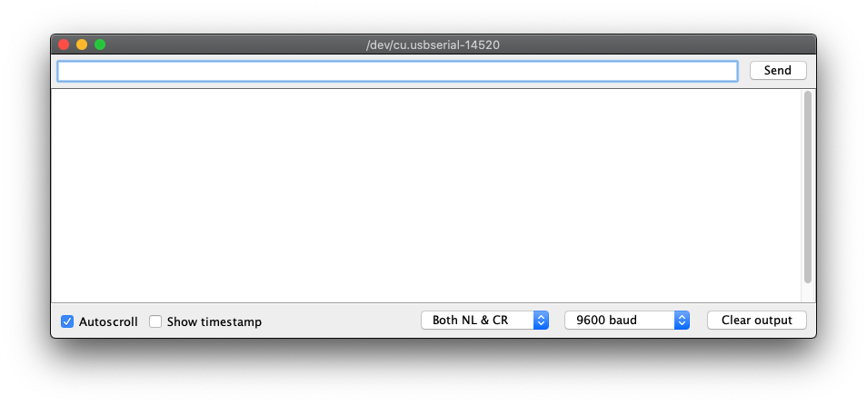
Make sure that the first drop-down box at the bottom is set to “Both NL & CR” and the second to “9600 baud”!
Now type “AT” in the text field at the top and hit Enter.
If everything is correct the AT command will be sent to the Bluetooth module and the Bluetooth module will respond with “OK” which will be sent back to the computer and visible in the serial monitor window.
Now you can see all available AT commands by typing “AT+HELP“. (on some devices it may be “AT HELP“)
You should see something like this:
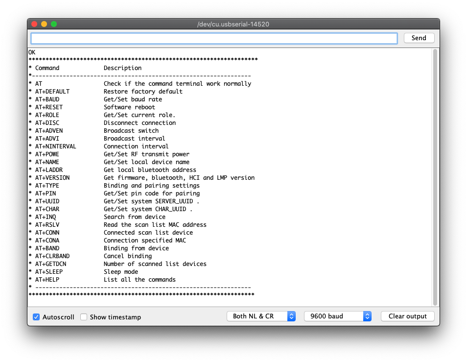
Most of the commands are Get/Set. This means that if you use the command without a value it will show the current value for this command.
There are four values we have to configure, and the best way will be to put them in the code, so they are configured on start.
To do this we need first to write a method that can send commands to the Bluetooth module. We already know how to send and receive so let’s put it all together:
1 2 3 4 5 6 7 8 9 10 11 12 13 14 15 16 17 18 19 | void sendCommand(const char * command) { Serial.print("Command send :"); Serial.println(command); mySerial.println(command); //wait some time delay(100); char reply[100]; int i = 0; while (mySerial.available()) { reply[i] = mySerial.read(); i += 1; } //end the string reply[i] = '\0'; Serial.print(reply); Serial.println("\nReply end"); delay(100); } |
The delays here are to give the Arduino and the Bluetooth module some time to send/receive the data.
The four parameters we need to configure are:
- the ROLE – sets master/slave role. Master is the one who initiates the connection, so we have to set the Bluetooth module to slave (ROLE 0). This is done with “AT+ROLE0“
- server UUID – needs to be set to “FFE0”. The command is “AT+UUIDFFE0” (more on this in the Android tutorial)
- characteristic UUID – needs to be set to “FFE1”. The command is “AT+CHARFFE1” (more on this in the Android tutorial)
- the name of the Bluetooth device. This is important to find the device. For BlueCArd the name of course is “BlueCArd” set with “AT+NAMEBlueCArd“
We have to set these parameters only once. That is why we can put this in the initBluetooth() function:
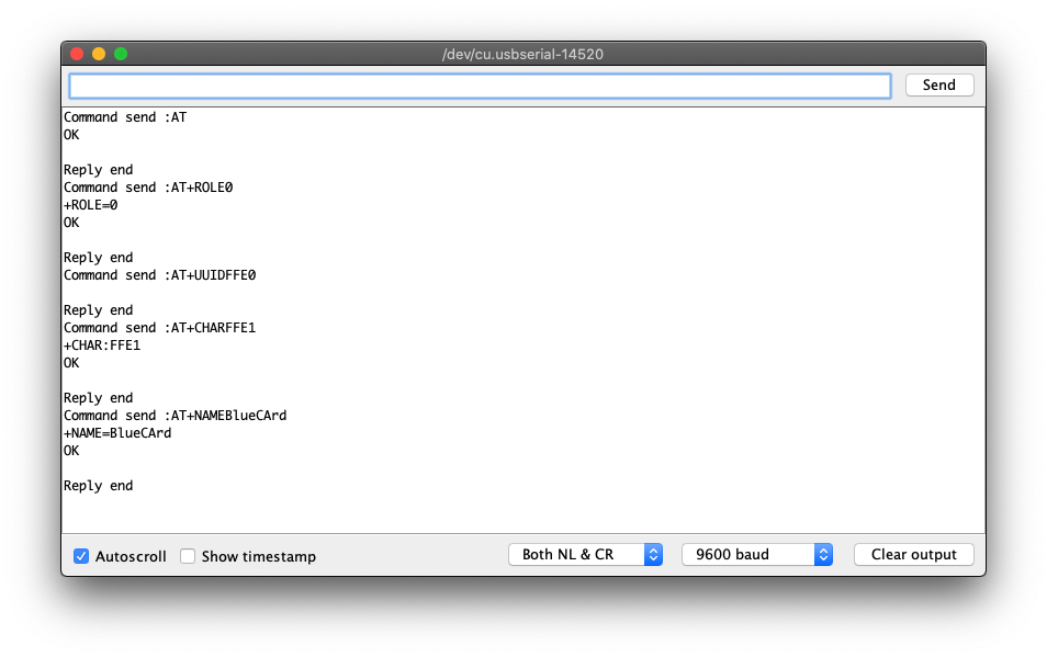
1 2 3 4 5 6 7 8 9 10 | void initBluetooth() { mySerial.begin(9600); Serial.begin(9600); sendCommand("AT"); sendCommand("AT+ROLE0"); sendCommand("AT+UUIDFFE0"); sendCommand("AT+CHARFFE1"); sendCommand("AT+NAMEBlueCArd"); } |
The “AT” call is just to test if everything is “OK“.
- Now close the Serial Monitor window if still open.
- Upload the sketch to the Arduino.
- Open the Serial Monitor again
The Bluetooth configuration should run automatically, and the Serial Monitor window should be something like this:
With this, the Arduino part of the Bluetooth setup is completed. You can find the source code from this tutorial on GitHub here:
https://github.com/nenovmy/arduino
in the “tutorial_05_connect_ble” folder.
Next Steps
In the next tutorial, I’ll show you how to connect to the Bluetooth module from Android and how to send commands from the Android phone to the Arduino Nano. At the end of the next tutorial, you will be able to control the led on the breadboard with your Android phone.
Previous: BlueCArd part 4 – What is a DC DC Boost Converter and why we need it
Next: BlueCArd part 6 – Controlling the Arduino BLE module from Android device


Leave a Reply
You must be logged in to post a comment.