


How to connect and control a DC Motor to an Arduino Nano using an H-Bridge and how to send commands from Android to the Arduino Nano microcontroller to control the DC Motor.

This tutorial is part of the BlueCArd tutorials series with the ultimate goal to build the BlueCArd Arduino-based RC car controlled from an Android phone through Bluetooth.
In this tutorial, I’ll explain how an H-Bridge works and how to use it to control a DC motor. Then I’ll show You how to extend the Android App to control the dc motor from an Android device.
Please use the board from the last tutorial: BlueCArd – part 6 – Controlling the Arduino Nano Bluetooth module from Android device
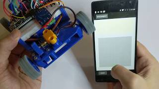
This is a short video of the DC Motor in action:
For this tutorial we also need:
- 1x H-Bridge
- 4x pin connector cables
- 1x DC motor (with cables)
What is an H-Bridge?
The digital pins on an Arduino Nano board have a constant output voltage of 5V. To be able to change the power output delivered to the connected circuit some pins support a PWM signal.
Using PWM signal and a MOS FET we can control the power delivered to a DC motor from a power source when we use a circuit similar to this one:

Now changing the PWM we can change the power to the motor M, but we can’t reverse the direction.
To reverse the direction, we need to change the polarity of the power supply. To do this we need an H-Bridge.
A schematic of an H-Bridge looks like this:
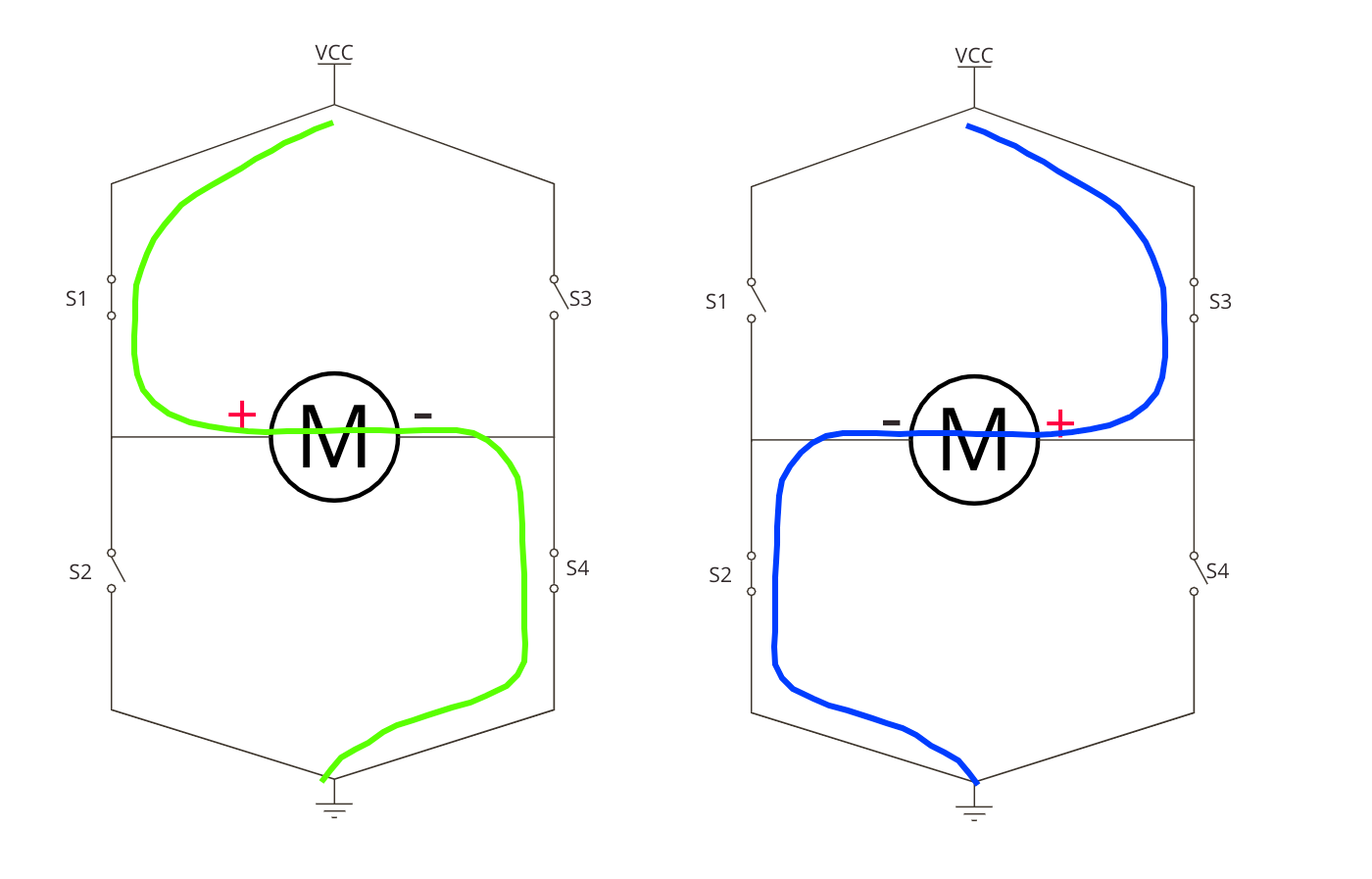
There are four switches. To control the H-Bridge we need only two signals because the switches are controlled in pairs.
- When S1 and S4 are closed and S2 and S3 are open the current flows from left to right
- When S1 and S4 are open and S2 and S3 are closed the current flows from right to left
In this way, we can change the polarity of the motor by using the right switch.
In an integrated circuit, transistors are used as switches.
I used for BlueCArd this Motor Driver board:

It is cheap and is sold everywhere.
This board has two H-Bridges (L9110S) integrated. With it, you can either control two separate DC motors or one stepper motor.
Connect the H-Bridge as follow:
- connect the motor at MB as shown in the image above.
- Connect the VCC to the 5V output of the DC-DC Boost converter.
- Connect the GND to one of the GND pins.
- Connect the blue wire to the D5 pin of the Arduino Nano
- Connect the orange wire to the D6 pin of the Arduino Nano
For the inputs IA and IB, these are the possible states of the outputs:
IA  IB  Output
Lo  Lo  Off
Hi  Lo  Forward
Lo  Hi  Reverse
Hi  Hi  Off
Now if we assume that IA is the speed and IB is the direction we can control a DC motor as follows:
Move forward:
IA set to HIGH (5V stable)
now we can use PWM on IB
- IB = 255 is equal to no power (see truth table)
- We can now decrease the PWM number of IB to increase the power to the motor (e.g. 128 is 50%)
- IB = 0 is the maximum power
Move backward:
IA set to LOW (0V stable)
now we can use PWM on IB
- IB = 0 is equal to no power (see truth table)
- Increasing IB will also increase the power with 128 being 50%
- IB = 255 is the maximum power
With this in mind, we can now write some code.
Arduino DC Motor control code
first, we have to decide how to send the data from the Android device to the Arduino microcontroller.
The motor can be powered forward or backward, so it makes sense to use only one command.
For this, I decided to encode the data in one byte.
- If the value is bigger than 128 the motor should drive forward (128 being off and 255 being full power)
- If the value is smaller than 128 the motor should drive backward (128 being off and 0 being full power)
With this in mind, we can control the motor with the following code:
1 2 3 4 5 6 7 8 9 10 11 12 13 14 15 16 17 18 19 20 21 22 23 24 25 | void motorPower(int fb) { if(fb == 128) stopMottors(); else if(fb > 128) moveForward(fb); else moveBackwards(fb); } void stopMottors() { digitalWrite( motorDir, LOW ); // Set motor to off digitalWrite( motorPWM, LOW ); } void moveForward(int fb) { digitalWrite( motorDir, HIGH ); // direction = forward int pow = 255 - ((fb - 128) * 2); analogWrite( motorPWM, pow ); } void moveBackwards(int fb) { digitalWrite( motorDir, LOW ); // direction = backwards int pow = 255 - (fb * 2); analogWrite(motorPWM, pow); } |
In this code, we first check in which direction to move.
If we move forward, we have to transform the byte in forward power. The value now has the following logic:
- 128 = off
- 255 = full power
but we need this:
- 255 = off
- 0 = full power
to do this we first scale the value (128 – 255) to (0 – 255) and then reverse it with 255 – scaled value.
The reverse is similar.
Also, I defined a new steering command that will be sent from Android:
1 | const int STEER = 0x3; |
With this, the Arduino side is finished and all that is left is the
Android Side
In the Android app, I made a view that looks like this:
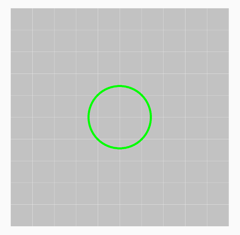
The green circle here is the joystick. The User can touch it and move it up and down to accelerate or drive backward.
Here we have to map the vertical circle position to the byte format from the previous section.
This means that we have to map the bottom position as 0 and then rise up to 255 at the top.
First, we normalize the y value (y = y pos/height) and then we can convert it to the required format with this function:
1 2 3 | private byte convertToByte(float v) { return (byte)(128 + Math.round(v * 127f)); } |
Now we can send the command to Arduino using the methods we developed in the last tutorial:
1 2 3 | public void steer(byte fb) { this.bleController.sendData(createControlWord(STEER, fb)); } |
here createControlWord(STEER, fb) method creates the right command array with one parameter automatically.
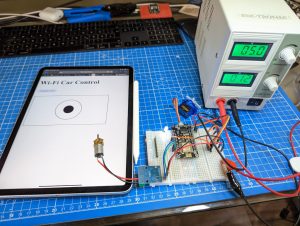
And that is all. Now we can control a DC motor from Android. Here is how it works:
With this, the Android part is completed. You can find the source code for this tutorial on GitHub here:
https://github.com/nenovmy/ardcar
Next Steps
With this, we are almost ready with the electronic and the software for BlueCArd.
In the next tutorial, I’ll show you how to connect a servo motor to Arduino Nano and then control it from Android.
Previous: BlueCArd part 6 – Controlling the Arduino BLE module from Android device
Next: BlueCArd part 8 – Controlling a Servo Motor from Arduino with an Android device


Leave a Reply
You must be logged in to post a comment.