


How to connect a servo motor to an Arduino Nano microcontroller and how to control it from an Android device using Bluetooth Low Energy (BLE).

This tutorial is part of the BlueCArd tutorials series with the ultimate to build the BlueCArd Arduino-based RC car controlled from an Android phone through Bluetooth.
In this tutorial, I’ll explain what is a servo motor and how to connect it to an Arduino microcontroller. I will also show you how to control it remotely from an Android device.
This is the last tutorial about the electronics of BlueCArd.
Please use the board from the last tutorial: Using H-Bridge to control a DC Motor from Arduino Nano
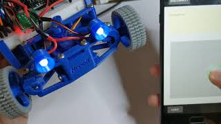
This is a short video of the Servo Motor in action:
For this tutorial we also need:
- 1x servo motor
What is a servo motor?
Servo motors are DC motors that can rotate to a given degree of rotation with great precision. They are perfect for steering.
I used for BlueCArd this Servo Motor:
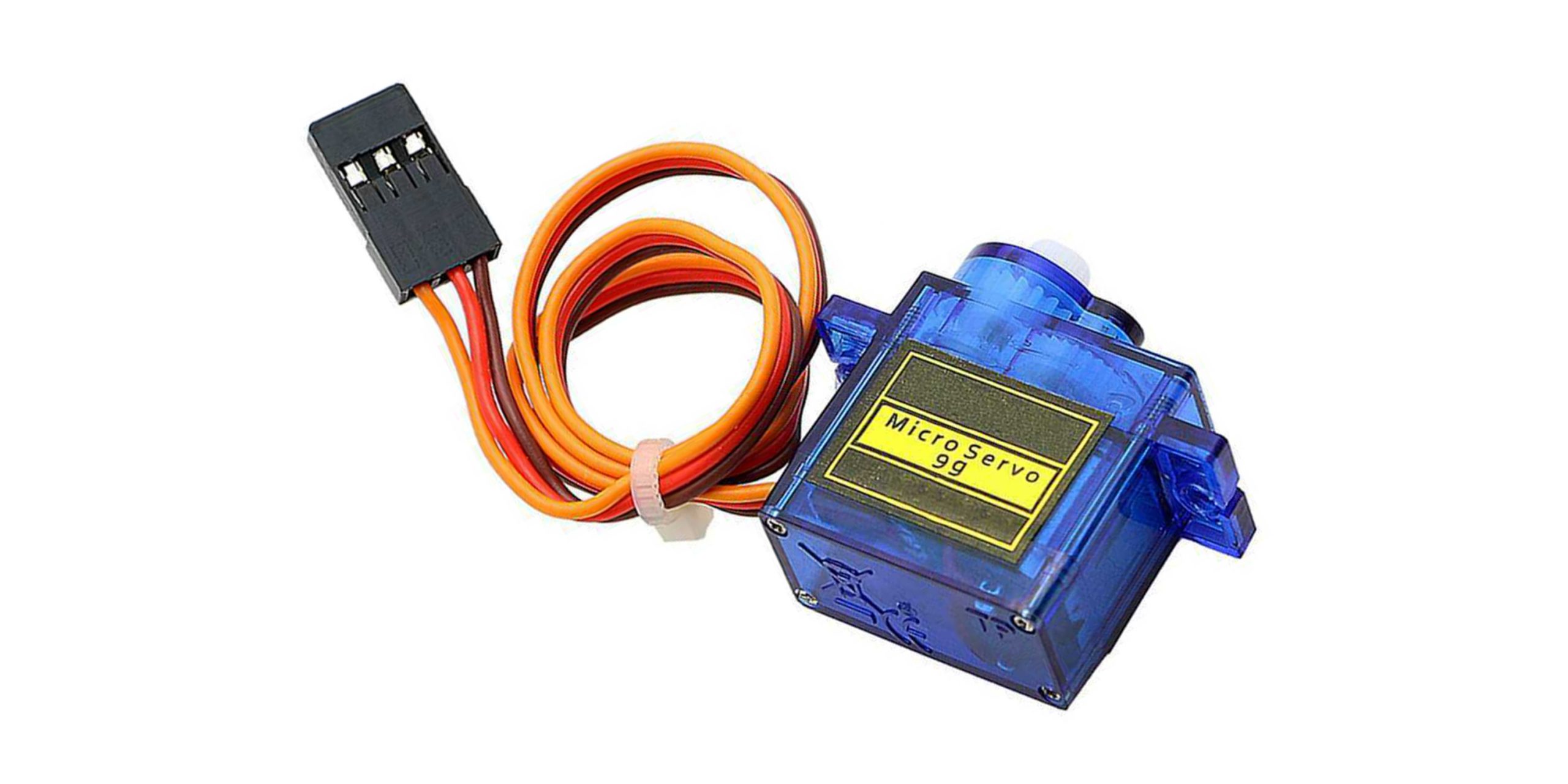
It is cheap bud solid and easy to use.
The servo motor has three cables.
Power supply – GND and VCC. The servo motor has a very high stall current. The DC-DC Boost Converter can’t deliver the required stall current, so we can’t use it here.
The good news is that this motor requires from 3.5V to 6V input voltage. This means that we can connect it directly to the battery pack (3×1,2V = 3.6V)
The third cable is for control. I used pin D12 for this.
Although a servo motor is controlled with PWM it doesn’t need a PWM pin. The servo library takes care of the control.
With this everything is connected. Now we have to write some code to make it work.
Arduino Code to control the Servo Motor
To control the servo motor we will use the Servo class from the Arduino servo library “Servo.h“.
Warning: this library has a problem with the software serial we are using for Bluetooth communication. It will work, but the servo motor will flinch every time data is sent. We can avoid this by using a PWM library (like PWMServo) that uses the PWM pins instead of interrupts. The usage is the same, you only have to change Servo.h to PWMServo.h and Servo class to PWMServo. Also with PWMServo You can use only PWM pins (on the Nano these are pins D9 and D10).
You can download the PWMServo library from GitHub: https://github.com/PaulStoffregen/PWMServo
1 2 3 4 5 6 7 8 9 10 11 12 13 14 15 16 17 18 19 | // include the library #include "Servo.h" // ... // Servo pin const int servoPin = 12; // ... // create servo object Servo servo; // ... //Init servo in initController() void initController() { servo.attach(servoPin); } |
With this, the servo is initialized.
The servo motor is controlled with the write(byte angle) method. Where the angle is in degrees and between 0 and 180.
We will send from Android the right value, so all we have to do in the Arduino sketch is to pass this value to the servo.write(angle) method.
Android Side
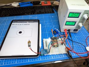
This is the control in the android app:

As you can remember from the previous tutorial sliding the green circle up and down controls the DC motors for forward and backward.
Sliding the circle left and right should control the servo motor. What we have to do is to map the horizontal coordinates to degrees like this:
90 degrees is straight (default position) so width / 2 should be 90.
We want to rotate to +/- 70 degrees. From this 0 should be -70 and width should be 70:
Using the steering control from above we actually change almost always the speed and the steering simultaneously. This means that it is a good idea to send both commands together. For this in the controller I wrote the steer() method with two variables for speed and steering left/right:
1 2 3 | public void steer(byte lr, byte fb) { this.bleController.sendData(createControlWord(STEER, lr, fb)); } |
With this, the control of BlueCArd is finished.
One more thing to do is to disable the motors/lights when the Bluetooth connection is lost. To do this we can use the STATE pin on the Bluetooth module and monitor when it gets from 1 to 0 or we can send a heartbeat signal from the Android and if we don’t receive it for some time assume that the connection is lost.
I implemented the second variant because I bought a BLE device with a STATE pin that wasn’t working.
Here is the servo motor in action:
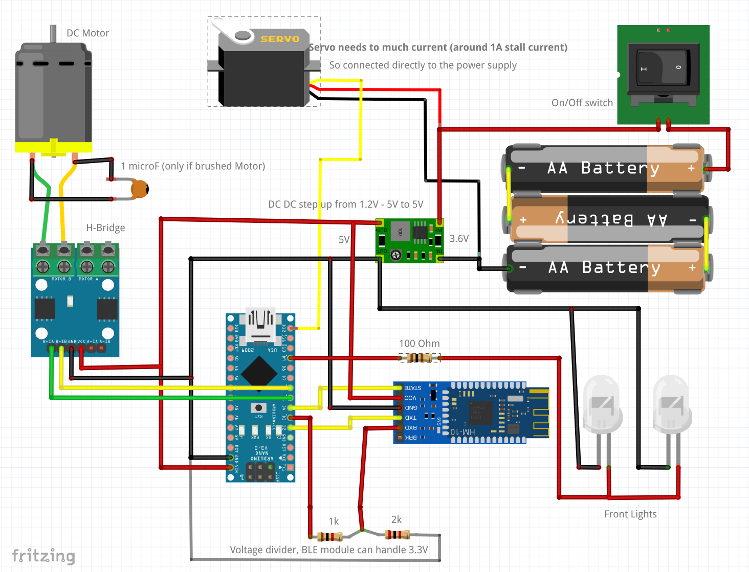
With this, the electronics and the software for the BlueCArd RC car are finished.
this is a circuit overview of all the elements we connected and programmed in this and the previous chapters:
The source code for the Arduino sketch and the Android app can be downloaded from Github here:
https://github.com/nenovmy/ardcar
Next Steps
The next tutorial will be the final tutorial where I’ll show you how to assemble the BlueCArd from the printed elements and the electronics together.
Previous: BlueCArd part 7 – using H-Bridge to control a DC Motor from Arduino Nano
Next: BlueCArd part 9 – the ultimate Print and Assembly manual


Leave a Reply
You must be logged in to post a comment.